Laser radar

A laser radar and laser beam technology, applied in the field of optical instruments, can solve the problems of reduced power ratio, reduced laser radar resolution or frame rate, etc., to achieve the effect of increasing the safe distance

Pending Publication Date: 2019-11-01
HESAI TECH CO LTD
View PDF7 Cites 6 Cited by
  • Summary
  • Abstract
  • Description
  • Claims
  • Application Information

AI Technical Summary

Problems solved by technology

[0006] In the prior art, there are many methods for reducing the damage of lidar to human eyes and reducing the safety distance, for example, increasing the aperture of the outgoing beam, so that ...

Method used


Image

  • Laser radar
  • Laser radar
  • Laser radar

Examples


Embodiment Construction

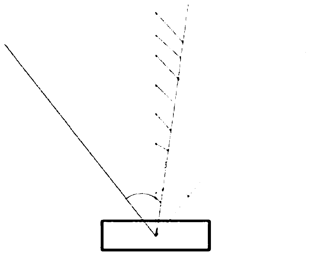
[0036] According to the analysis in the background technology section, it can be seen that by setting multiple optical paths of the lidar and splicing the multiple sub-scanning fields of view collected by it, the lidar can obtain a larger field of view. There is usually a certain overlapping area between adjacent sub-scanning fields of view, such as figure 1 As shown in , the part marked with oblique lines is the overlapping area between two adjacent sub-scanning fields of view.

[0037] In the overlapping area between adjacent sub-scanning fields of view, the power of the laser beam entering the pupil of the human eye is the linear superposition of the power of the two laser beams entering the pupil of the human eye respectively, which will lead to a large increase in the safety distance of the lidar. (that is, the human eye needs to be farther away from the light source of the lidar to avoid being damaged by the laser).

[0038] In the existing technology, the method of red...


PUM

PropertyMeasurementUnit
Wavelengthaaaaaaaaaa

Abstract

A laser radar comprising a laser emitting module, a beam splitting module, a scanning module and receiving modules, wherein there are a plurality of receiving modules, the scanning module correspondingly forms a plurality of sub-scanning fields of view respectively with the plurality of receiving modules, the plurality of sub-scanning fields of view form a total field of view of the laser radar byfield-of-view splicing; and the exiting position of the laser beam corresponding to the adjacent sub-scanning fields of view on the scanning module satisfies a preset distance condition. In the invention the laser radar for splicing a plurality of sub-scanning fields of view only needs to modify the structure of the laser radar to a small extent to limit that the exiting position of the laser beam corresponding to the adjacent sub-scanning fields of view on the scanning module meets the preset distance condition, thereby, without affecting the performance of the laser radar, avoiding/reducingthe large increase in the safety distance due to the overlapping area between adjacent sub-scanning fields of view.

Description

technical field [0001] The invention relates to the technical field of optical instruments, in particular to a laser radar. Background technique [0002] In autonomous driving technology, vehicles can perceive surrounding objects with the help of devices such as lidar. The working principle of the laser radar is to emit a laser beam to the surrounding three-dimensional space as a detection signal. Signals are compared to obtain relevant information about the object to be measured, such as distance, speed, etc. [0003] As we all know, intense laser can cause damage to human eyes. For this reason, my country has relevant human eye safety standards to limit the abuse of laser. LiDAR needs to choose a suitable working wavelength, such as 1550nm, and its damage to the human eye is mainly thermal damage. According to the human eye safety standard, the eye safety power threshold of a laser is related to parameters such as laser wavelength, spot size, and number of pulses. [0...

Claims


Application Information

Patent Timeline
IPC IPC(8): G01S7/481
CPCG01S7/4817
Inventor 吴世祥向少卿
Owner HESAI TECH CO LTD
Why Eureka
Try Eureka