
A new lithium battery structure

A lithium battery, a new type of technology, applied in structural parts, secondary batteries, battery pack parts, etc., can solve problems such as troublesome operation, inability to improve service life, battery fire, etc., to prevent heat diffusion, improve heat dissipation effect, The effect of increasing energy density

Active Publication Date: 2022-03-18
江西力能新能源科技有限公司
View PDF9 Cites 0 Cited by
  • Summary
  • Abstract
  • Description
  • Claims
  • Application Information

AI Technical Summary

Problems solved by technology

[0002] Lithium battery is a type of battery that uses lithium metal or lithium alloy as the negative electrode material and uses a non-aqueous electrolyte solution. Due to the very active chemical properties of lithium metal, the processing, storage and use of lithium metal have very high environmental requirements, but With the development of science and technology, lithium batteries have become the mainstream now; existing lithium batteries have certain disadvantages in use, first of all, it is impossible to avoid short circuits caused during use, and it is difficult to reduce the corrosion of electrode terminal materials , so that the service life cannot be improved, and the electrolyte cannot be replaced at the same time, it is difficult to increase the utilization rate of the battery, and finally the safety performance of the battery cannot be improved. Lithium dendrites generated during the use of the battery will pierce the diaphragm, resulting in a short circuit, causing unsafe phenomena such as fire, explosion, and scrapping of the battery

Method used


Image

  • A new lithium battery structure
  • A new lithium battery structure
  • A new lithium battery structure

Examples


Embodiment 1

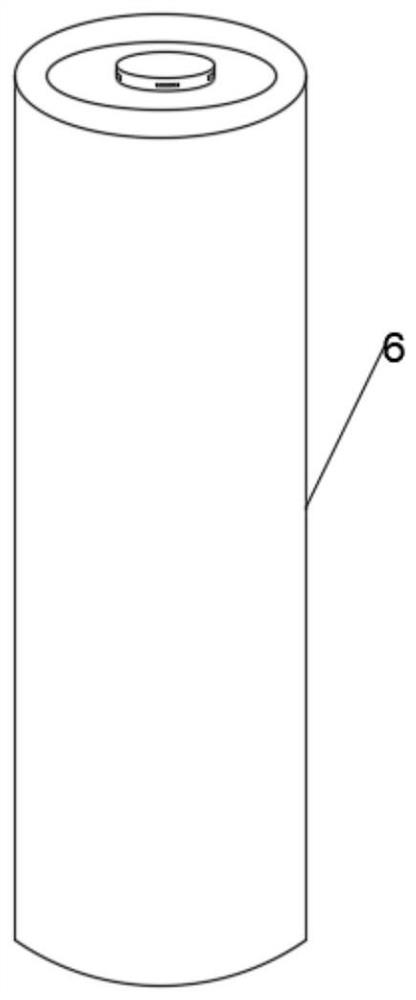
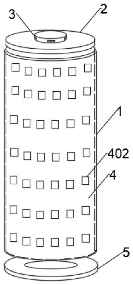
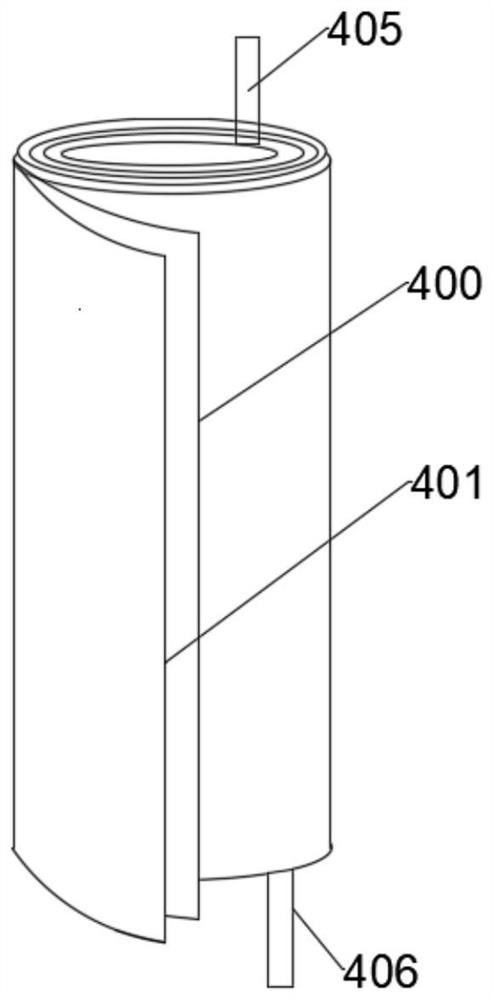
[0034] Such as Figure 1-6 As shown, a new type of lithium battery structure includes a battery body 4, the battery body 4 includes a positive electrode sheet 400 and a negative electrode sheet 401 that are sequentially wound from the inside to the outside, and the negative electrode sheet 400 is provided with a current collector 4012, The current collector 4012 is welded with a negative tab 406, the positive tab 401 is provided with a positive tab 405, and the upper and lower surfaces of the negative tab 400 are coated with a 5-10 micron ceramic coating 407;

[0035] The upper surface of the battery body 4 is equipped with a positive electrode cap 2, and the side surface of the positive electrode cap 2 is uniformly provided with through holes 3;

[0036] The outer surface of the battery main body 4 is provided with a casing 1, the casing 1 is cylindrical, the casing 1 is filled with electrolyte, the battery main body 4 is immersed under the liquid surface of the electrolyte, ...

Embodiment 2

[0038] This embodiment is a further optimization made on the basis of Embodiment 1, as Figure 5 As shown, specifically, the surface of the ceramic coating 407 is coated with at least one strip-shaped barrier coating 4011 extending continuously along the length direction of the negative electrode sheet 401 .

[0039] The strip-shaped barrier coating 4011 passes through the negative tab 406 .

[0040] The outer wall of the housing is provided with a plurality of protrusions 402 arranged in a matrix.

[0041] The strip-shaped barrier coating 4011 has a thickness of 3-9 μm, preferably 5 μm. The strip-shaped barrier coating 4011 is in the shape of a single straight line or two straight lines or wavy lines. If necessary, multiple barrier coatings can be set according to the electrode reaction , and can have forks. The coating of the barrier coating 4011 on the surface of the positive electrode sheet 403 may adopt techniques such as pad printing, screen printing, and spray coating...

Embodiment 3

[0043] This embodiment is a further optimization made on the basis of Embodiment 2, and the preparation method of the ceramic coating 407 is as follows:

[0044] S1: Add the ceramic mixed powder, dispersant and water into the ball mill, ball mill for 0.5h, then add the binder, and continue ball milling for 20min to prepare the slurry;

[0045] S2: coating the slurry obtained after dispersion on both sides of the lithium battery negative electrode sheet 401, the thickness of the coating layer is 5 μm;

[0046] S3: drying: put the negative electrode sheet 401 coated in step S3 into a vacuum drying oven for drying.

[0047] The ceramic mixed powder is a mixed powder of boehmite and silicon dioxide in a mass ratio of 1:1.

[0048] Calculated by weight, 100 parts of ceramic mixed powder, 0.5 parts of dispersant, 3 parts of binder, and 500 parts of water.

[0049] The dispersant is selected from ammonium polyacrylate.

[0050] The binder is sodium carboxymethyl cellulose.

[0051]...


PUM

PropertyMeasurementUnit
thicknessaaaaaaaaaa
thicknessaaaaaaaaaa

Abstract

The invention discloses a novel lithium battery structure, which includes a battery main body. The battery main body includes a positive electrode piece and a negative electrode piece wound in sequence from the inside to the outside. A current collector is arranged on the negative electrode piece. Positive tabs are provided, and the upper surface and the lower surface of the negative plate are coated with a 5-10 micron ceramic coating; the upper surface of the battery body is equipped with a positive cap, and the side surface of the positive cap is uniformly provided with through holes; the outer surface of the battery body A casing is provided, the casing is cylindrical, and electrolyte is injected into the casing, the main body of the battery is immersed under the liquid surface of the electrolyte, the upper surface of the casing is provided with a positive cap, the positive ear is connected to the positive cap, and the negative ear is connected to the bottom of the casing. An insulating gasket is provided on the lower surface of the casing, and a cladding layer is provided outside the casing, which can fix the casing and the insulating gasket. The invention can save the setting of the diaphragm, reduce the cost, increase the energy density, and improve the safety factor. .

Description

technical field [0001] The invention belongs to the field of batteries, in particular to a novel lithium battery structure. Background technique [0002] Lithium battery is a type of battery that uses lithium metal or lithium alloy as the negative electrode material and uses a non-aqueous electrolyte solution. Due to the very active chemical properties of lithium metal, the processing, storage and use of lithium metal have very high environmental requirements, but With the development of science and technology, lithium batteries have become the mainstream now; existing lithium batteries have certain disadvantages in use, first of all, it is impossible to avoid short circuits caused during use, and it is difficult to reduce the corrosion of electrode terminal materials , so that the service life cannot be improved, and the electrolyte cannot be replaced at the same time, it is difficult to increase the utilization rate of the battery, and finally the safety performance of the...

Claims


Application Information

Patent Timeline
Patent Type & Authority Patents(China)
IPC IPC(8): H01M10/0587H01M10/42H01M50/102H01M50/116H01M10/613H01M10/6562
CPCH01M10/0587H01M10/4235H01M10/613H01M10/6562H01M50/10Y02E60/10Y02P70/50
Inventor 侯伟侯民郭农庆
Owner 江西力能新能源科技有限公司
Learn More