Method and device for detecting rotor position of permanent magnet synchronous motor and ventilation treatment device

A technology for permanent magnet synchronous motors and synchronous motors, which is applied in electrical components, motor control, electronic commutation motor control, etc., and can solve the problems of reducing motor drive efficiency, reducing the accuracy of three-phase current measurement of motors, and low detection accuracy of motor rotor positions. problem, to achieve the effect of improving efficiency

Inactive Publication Date: 2019-11-01
BMCTIANJIN MEDICAL CO LTD
View PDF4 Cites 0 Cited by
  • Summary
  • Abstract
  • Description
  • Claims
  • Application Information

AI Technical Summary

Problems solved by technology

However, for a permanent magnet synchronous motor with a small inductance, due to the large current ripple, it is easy to generate additional noise, and it is easy to reduce the measurement accuracy of the three-phase current of the motor, making the detection accuracy of the motor rotor position low , and in turn, it may also reduce the driving efficiency of the motor

Method used


Image

  • Method and device for detecting rotor position of permanent magnet synchronous motor and ventilation treatment device
  • Method and device for detecting rotor position of permanent magnet synchronous motor and ventilation treatment device
  • Method and device for detecting rotor position of permanent magnet synchronous motor and ventilation treatment device

Examples


Embodiment 1

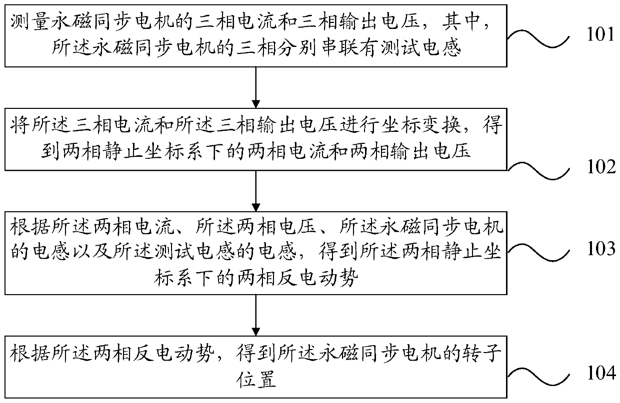
[0032] refer to figure 1 , which shows a flow chart of the steps of an embodiment of a method for detecting the rotor position of a permanent magnet synchronous motor according to the present invention, which may specifically include the following steps:

[0033] Step 101: Measure the three-phase current and three-phase output voltage of the permanent magnet synchronous motor, wherein the three phases of the permanent magnet synchronous motor are respectively connected in series with test inductance.

[0034] In the embodiment of the present invention, before observing the counter electromotive force of the permanent magnet synchronous motor, the inductance can be tested in series on the three phases of the permanent magnet synchronous motor respectively, and the inductance L of the test inductor connected in series for each phase on the three phases S equal.

[0035] In practical applications, the three-phase current I of the permanent magnet synchronous motor can be measure...

Embodiment 2

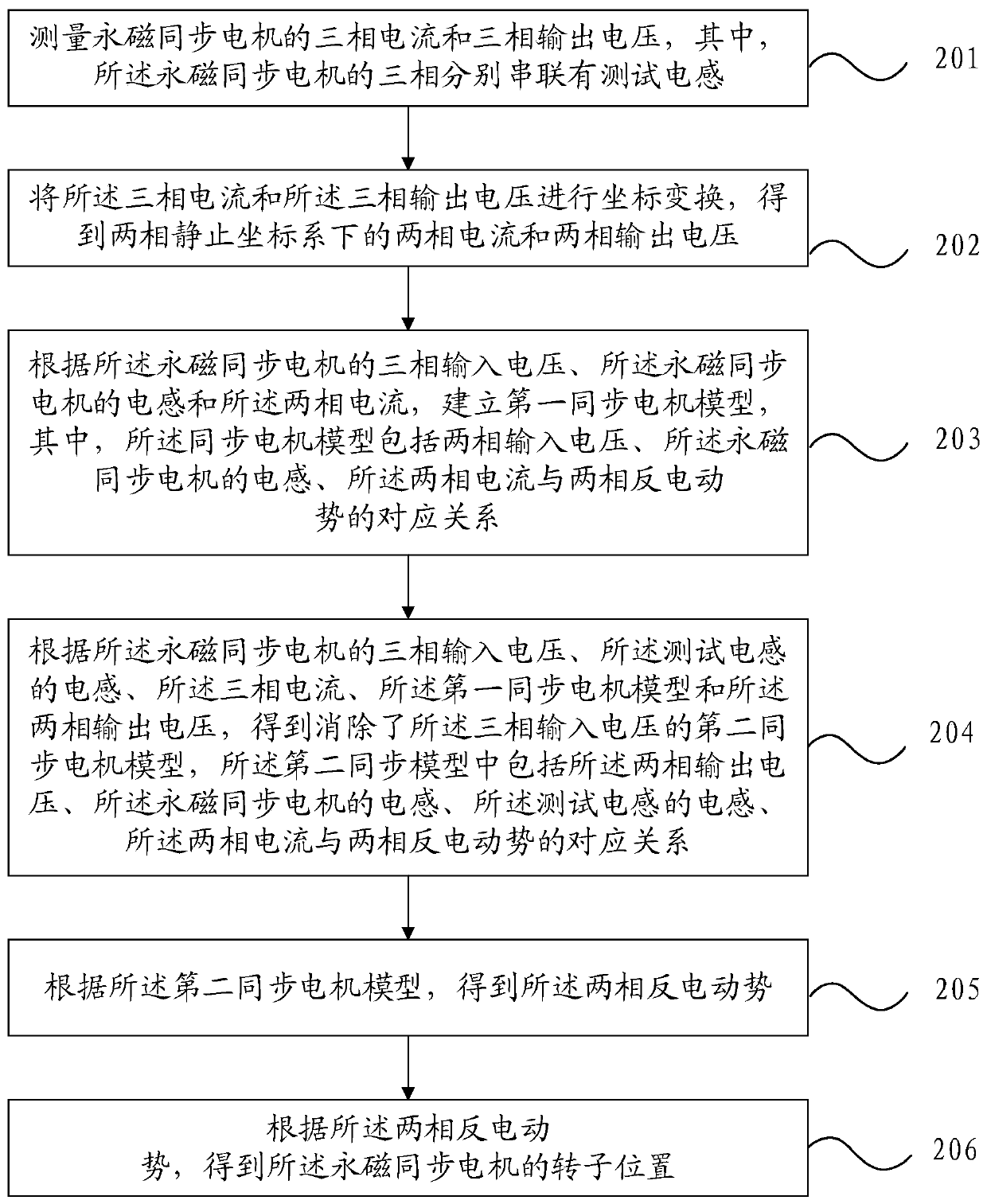
[0059] refer to figure 2 , which shows a flow chart of the steps of another embodiment of the method for detecting the rotor position of a permanent magnet synchronous motor according to the present invention, which may specifically include the following steps:

[0060] Step 201: Measure the three-phase current and three-phase output voltage of the permanent magnet synchronous motor, wherein the three phases of the permanent magnet synchronous motor are respectively connected in series with test inductors.

[0061] Specifically, for the specific implementation process of step 201, refer to step 101 in the first embodiment, and details are not repeated here.

[0062] Step 202: Perform coordinate transformation on the three-phase current and the three-phase output voltage to obtain the two-phase current and the two-phase output voltage in the two-phase stationary coordinate system.

[0063] Specifically, for the specific implementation process of step 202, refer to step 102 in...

Embodiment 3

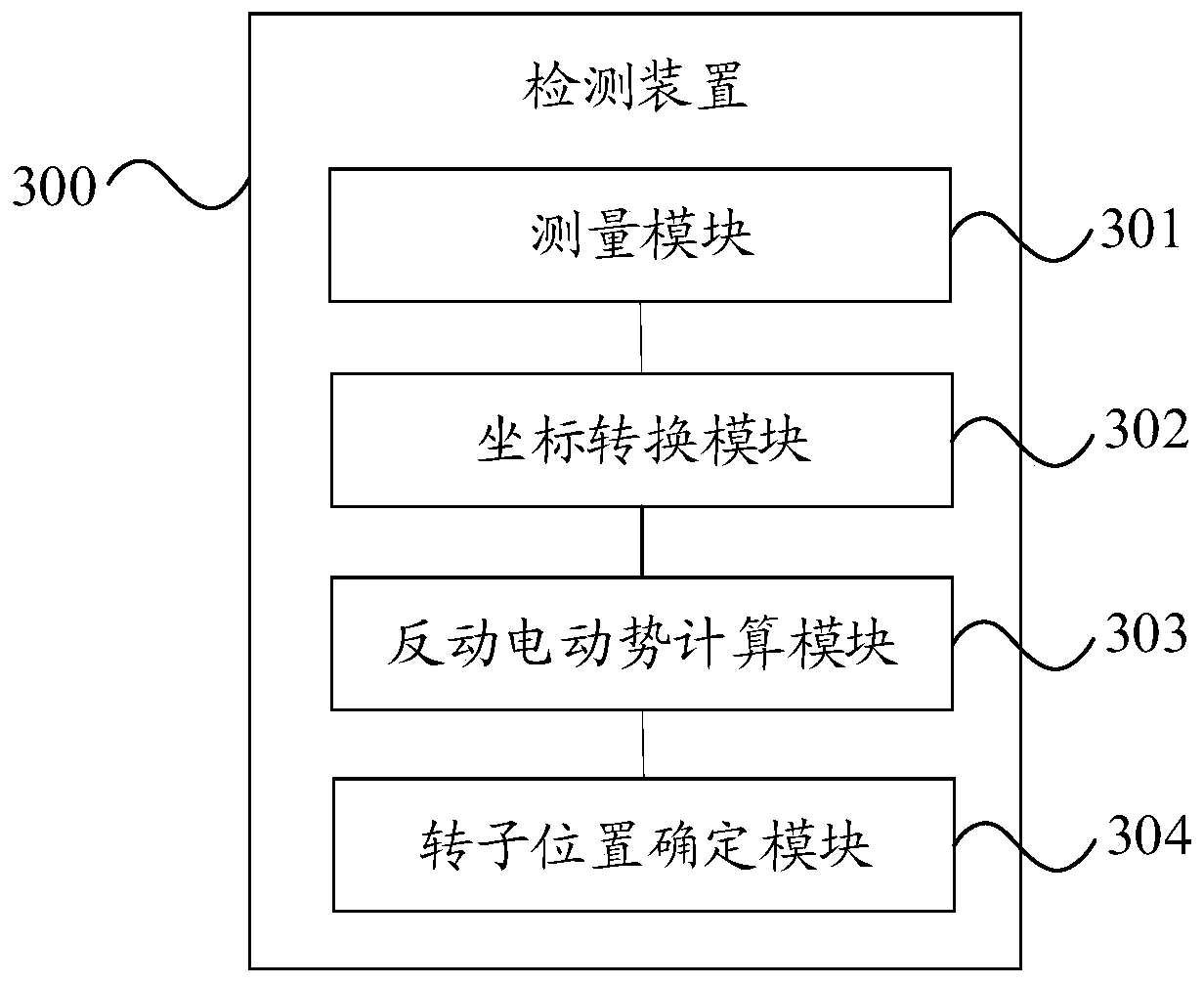
[0113] refer to image 3 , which shows a structural block diagram of an embodiment of a detection device for the rotor position of a permanent magnet synchronous motor according to the present invention. The detection device 300 may specifically include the following modules:

[0114] The measurement module 301 is used to measure the three-phase current and the three-phase output voltage of the permanent magnet synchronous motor, wherein the three phases of the permanent magnet synchronous motor are respectively connected in series with test inductors.

[0115] The coordinate conversion module 302 is configured to perform coordinate transformation on the three-phase current and the three-phase output voltage to obtain the two-phase current and the two-phase output voltage in the two-phase stationary coordinate system.

[0116] The counter electromotive force calculation module 303 is used to obtain the two opposite phases in the two-phase stationary coordinate system according...


PUM


Abstract

Embodiments of the present invention provide a method and a device for detecting a rotor position of a permanent magnet synchronous motor and a ventilation treatment device. The method comprises the steps of: measuring a three-phase current and three-phase output voltage of the permanent magnet synchronous motor, wherein the three phases of the permanent magnet synchronous motor are respectively connected in series with test inductors; performing coordinate transformation of the three-phase current and the three-phase output voltage to obtain a two-phase current and a two-phase output voltagein a two-phase stationary coordinate system; according to the two-phase current, the two-phase output voltage, the inductors of the permanent magnet synchronous motor and the inductors of the test inductors, obtaining the two-phase counter electromotive force in the two-phase stationary coordinate system; and according to the two-phase counter electromotive force, obtaining the rotor position of the permanent magnet synchronous motor. According to the embodiment of the invention, the current ripple of the permanent magnet synchronous motor is reduced, the observation precision of the two-phasecounter electromotive force is improved, and the detection accuracy of the rotor position of the permanent magnet synchronous motor is further improved.

Description

technical field [0001] The invention relates to the technical field of motors, in particular to a detection device for the rotor position of a permanent magnet synchronous motor and ventilation treatment equipment. Background technique [0002] Permanent magnet synchronous motors have the advantages of small size, high reliability, high power density and high efficiency, and have been widely used in industrial, medical, civil and national defense fields. Based on the problems of motor reliability, volume and cost, the position sensor is usually canceled on the permanent magnet synchronous motor. Therefore, in the control of the permanent magnet synchronous motor, the rotor position is usually detected to realize the field-oriented control of the permanent magnet synchronous motor and obtain better driving efficiency. [0003] In the existing technology, the rotor position is usually obtained by observing the counter electromotive force of the permanent magnet synchronous mo...

Claims


Application Information

Patent Timeline
Patent Type & Authority Applications(China)
IPC IPC(8): H02P6/182
CPCH02P6/182H02P2203/03
Inventor 易萍虎齐丹任尧庄志
Owner BMCTIANJIN MEDICAL CO LTD
Why Eureka
Try Eureka