Indoor electric energy router structure

A router and power technology, applied in electrical components, selection devices, etc., can solve problems such as large size, and achieve the effects of high power density, smooth power flow, and convenient transfer and transportation.

Pending Publication Date: 2019-11-01
TBEA XIAN ELECTRIC TECH +1
View PDF5 Cites 0 Cited by
  • Summary
  • Abstract
  • Description
  • Claims
  • Application Information

AI Technical Summary

Problems solved by technology

At present, the traditional power router is designed as an outdoor container design. Due to the overall volume of the container power router, it has limitations for indoor installation conditions.

Method used


Image

  • Indoor electric energy router structure
  • Indoor electric energy router structure
  • Indoor electric energy router structure

Examples


Embodiment Construction

[0017] The present invention will be described in detail below in conjunction with the accompanying drawings and specific embodiments.

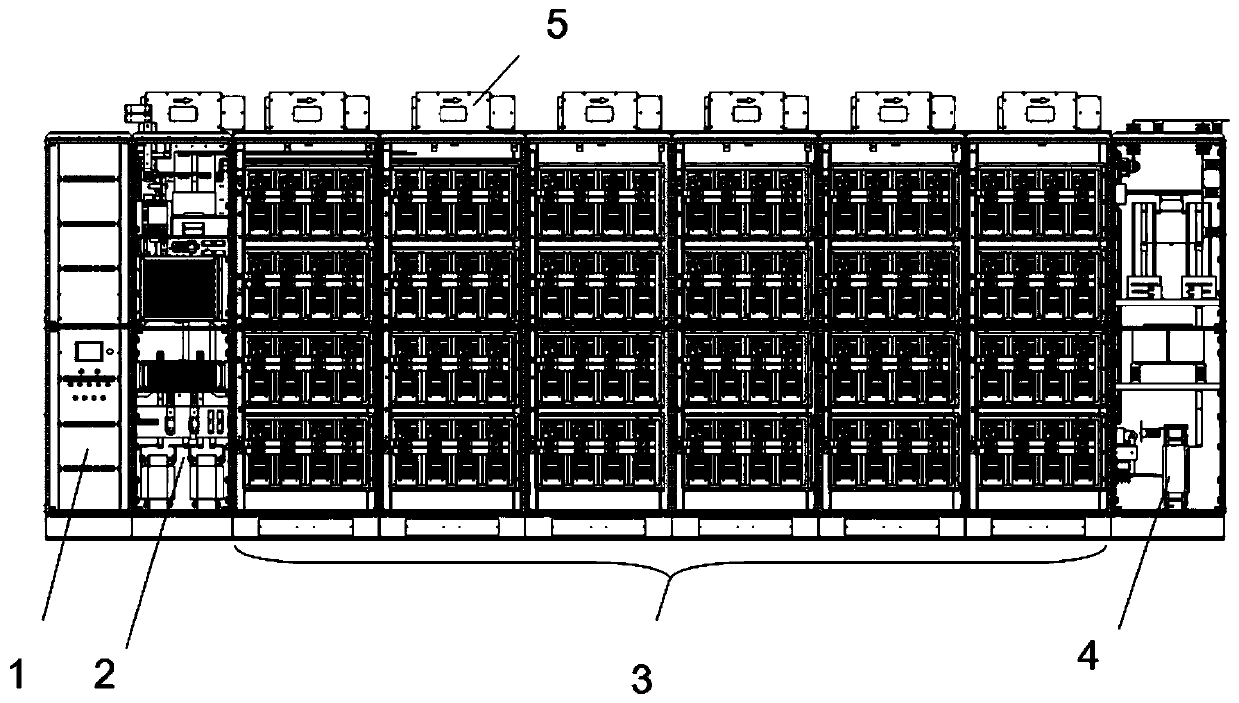
[0018] In describing the present invention, it should be understood that the terms "center", "longitudinal", "transverse", "upper", "lower", "front", "rear", "left", "right", " The orientations or positional relationships indicated by "vertical", "horizontal", "top", "bottom", "inner" and "outer" are based on the orientations or positional relationships shown in the drawings, and are only for the convenience of describing the present invention and Simplified descriptions, rather than indicating or implying that the device or element referred to must have a particular orientation, be constructed and operate in a particular orientation, and thus should not be construed as limiting the invention. In the present invention, "before" means figure 1 main viewing direction. In addition, the terms "first" and "second" are used for descriptive purpos...


PUM


Abstract

The invention discloses an indoor electric energy router structure which comprises a control cabinet, a BUCK cabinet, a plurality of power cabinets and a starting cabinet which are arranged in sequence. The control cabinet, the BUCK cabinet, the plurality of power cabinets and the starting cabinet are all combined cabinets. The BUCK cabinets are connected with the power cabinets through copper buses, and the power cabinets are connected with the starting cabinet through copper buses. The power cabinets are of a parallel structure, the number of the power cabinets can be superposed according topower requirements, and a plurality of power modules connected in parallel are arranged in the power cabinets. The whole machine is compact in structure and high in power density. Because power needsa huge cabinet body structure, the sub-cabinet design is convenient to transfer and transport, hoisting or plug-in mounting operation can be carried out on site, and cabinet combination processing iscarried out after the power reaches a specified position.

Description

technical field [0001] The invention belongs to the technical field of power electronics, and in particular relates to an indoor electric energy router structure. Background technique [0002] As an intelligent interface for distributed power sources, reactive power compensation equipment, energy storage equipment, loads, etc. in the distribution network, the power router should flexibly use structural design knowledge to innovate structural forms under the premise of ensuring power quality, so as to adapt to the operation of various equipment environment. At present, the traditional power router is designed as an outdoor container design. Due to the overall volume of the container power router, it has limitations for indoor installation conditions. Contents of the invention [0003] In order to solve the above problems, the present invention provides an indoor power router structure, which adopts an indoor design and adjusts according to the number of power modules to me...

Claims


Application Information

Patent Timeline
Patent Type & Authority Applications(China)
IPC IPC(8): H04Q1/02
CPCH04Q1/025H04Q1/032H04Q1/116
Inventor 胡亮杨武帝李直王娟
Owner TBEA XIAN ELECTRIC TECH
Why Eureka
Try Eureka