A kind of environment-friendly sputum recycling container
An environmentally friendly, recycling technology, applied in the field of machinery, can solve the problems of affecting sanitation, thick sputum, and difficulty in cleaning, etc., and achieve the effect of reducing sputum pollution, reducing sputum concentration, and facilitating sputum collection
- Summary
- Abstract
- Description
- Claims
- Application Information
AI Technical Summary
Problems solved by technology
Method used
Image

Examples
Embodiment 1
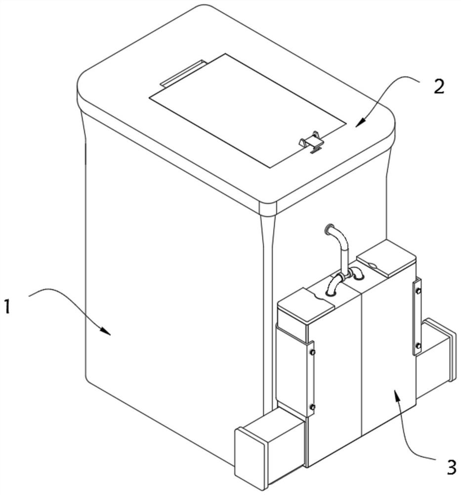
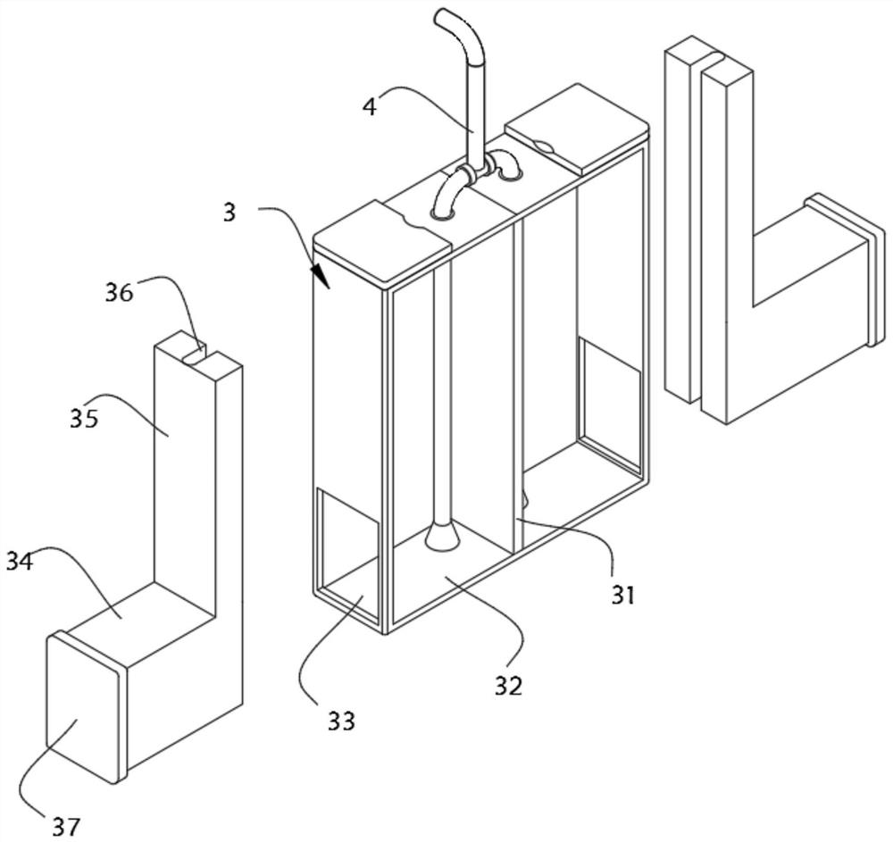
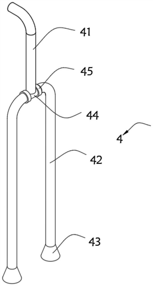
[0038] The invention provides an environment-friendly sputum recovery cylinder, such as Figure 1-Figure 3 with Figure 8-Figure 9 As shown, it includes a cylinder body 1, a cover body 2 installed on the top of the cylinder body 1, and a cleaning cylinder 3 arranged on the outer wall of the cylinder body 1. The inside of the cleaning cylinder 3 is a hollow structure, and the inner center of the cleaning cylinder 3 is installed with a Partition plate 31, partition plate 31 divides the internal space of cleaning cylinder 3 into a pair of liquid storage bins 32, and the two sides of the outer wall of cleaning cylinder 3 are respectively provided with push grooves 33 communicating with the inside thereof, and push blocks 34 are arranged in the push grooves 33, The push block 34 and the push groove 33 are slidably matched. One end of the push block 34 is integrally formed with an extruding plate 35, and the other end of the push block 34 is integrally formed with a push plate 37. T...
Embodiment 2
[0047] As the second embodiment of the present invention, in order to facilitate the addition of liquid in the cleaning cylinder 3, the inventors improved the structure of the cleaning cylinder 3, as a preferred embodiment, such as Figure 4 As shown, a pair of liquid filling slots 38 are provided on the top of the cleaning cylinder 3 , an insert block 39 is arranged in the liquid addition slot 38 , and a cover plate 310 is installed on the top of the insert block 39 .
[0048] In this embodiment, the inner side of the cover plate 310 is provided with a buckle groove 311 , so that the cover plate 310 can be opened from the liquid filling slot 38 through the buckle groove 311 .
[0049] Further, the inserting block 39 and the filling slot 38 are plugged together, so that the inserting block 39 is stuck in the filling slot 38 to realize the sealing of the filling slot 38 .
[0050] Specifically, the insert block 39 is made of silica gel material, which has a good sealing effect ...
Embodiment 3
[0053] As a third embodiment of the present invention, in order to facilitate the installation of the cleaning cylinder 3, the inventor is also provided with a mounting bracket 5, as an embodiment, such as Figure 5-Figure 7 As shown, the cleaning cylinder 3 is installed on the outer wall of the cylinder body 1 through the mounting bracket 5. The outer wall of the cleaning cylinder 3 is provided with a plurality of thread grooves 312. The mounting bracket 5 is in a "U" shape as a whole. The card edge 51 is installed with a bolt 52 threadedly connected with the thread groove 312 .
[0054] In this embodiment, the mounting frame 5 is made of PP plastic material, which has good toughness, and is convenient to be clamped on the cleaning cylinder 3 by the toughness of the mounting frame 5 itself.
[0055] Further, the installation frame 5 and the cylinder body 1 are adhered and fixed, and the cylinder body 1 is fixedly installed on the installation frame 5 by means of adhesion, wit...
PUM
 Abstract
Description
Claims
Application Information
 - R&D
- Intellectual Property
- Life Sciences
- Materials
- Tech Scout
- Unparalleled Data Quality
- Higher Quality Content
- 60% Fewer Hallucinations
Browse by: Latest US Patents, China's latest patents, Technical Efficacy Thesaurus, Application Domain, Technology Topic, Popular Technical Reports.
© 2025 PatSnap. All rights reserved.Legal|Privacy policy|Modern Slavery Act Transparency Statement|Sitemap|About US| Contact US: help@patsnap.com