Automatic gluing device

A glue coating device and power device technology, which is applied to the surface coating liquid device, coating, metal processing equipment, etc., can solve the problems of large safety hazards, high labor intensity, low efficiency, etc., and achieve high-efficiency and automatic operation High degree, the effect of reducing potential safety hazards

Active Publication Date: 2021-11-30
中国兵器装备集团自动化研究所有限公司
View PDF17 Cites 0 Cited by
  • Summary
  • Abstract
  • Description
  • Claims
  • Application Information

AI Technical Summary

Problems solved by technology

[0003] The present invention provides an automatic gluing device in order to solve the technical problems of traditional propellant gluing and assembling process with high labor intensity, low efficiency and great potential safety hazards.

Method used


Image

  • Automatic gluing device
  • Automatic gluing device
  • Automatic gluing device

Examples


Embodiment 1

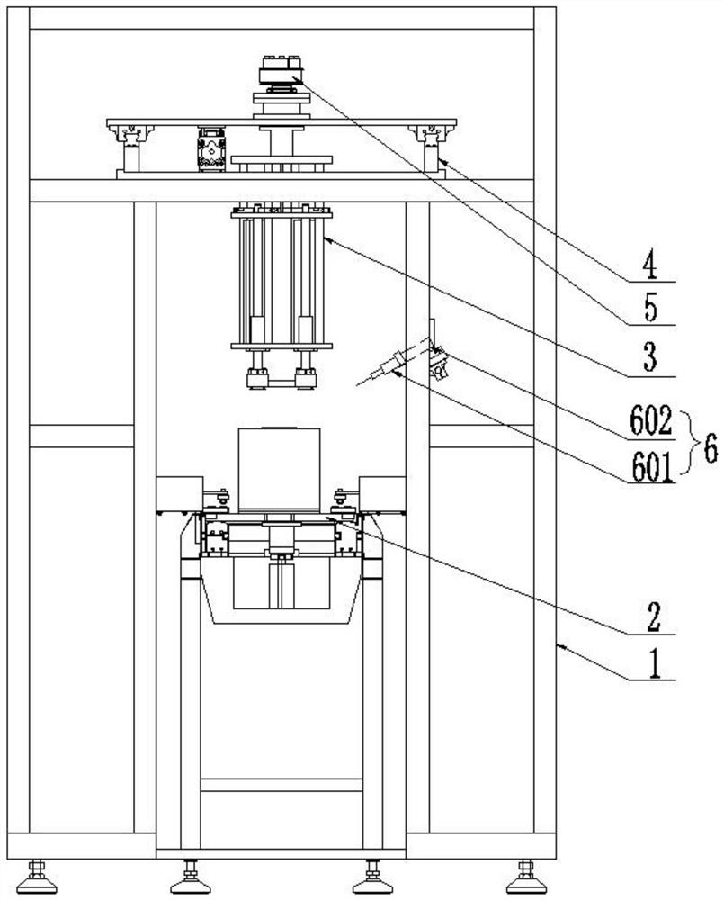
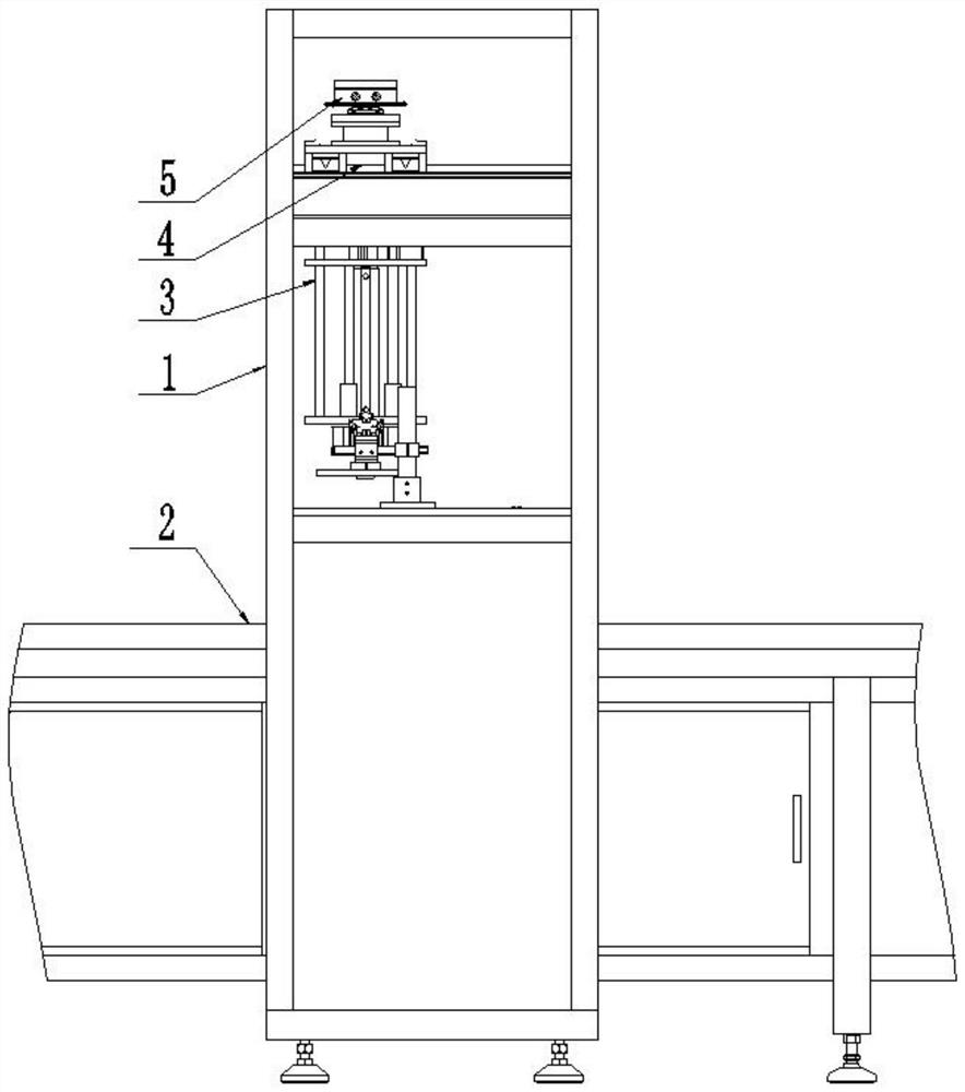
[0038] like figure 1 , figure 2 and image 3As shown, the automatic gluing device of the present invention includes a frame 1, a transmission line 2 arranged in the frame 1, a translation mechanism 4 arranged on the frame 1, a rotation mechanism 5 arranged on the translation mechanism 4, and a rotation mechanism 5. The grasping mechanism 3 connected by the mechanism 5 and the gluing mechanism 6 arranged on the frame 1, the grasping mechanism 3 and the gluing mechanism 6 are arranged above the transmission line 2, and the grasping mechanism 3 includes two fixed intervals. The top plate 301 and the bottom plate 302 arranged at a distance and parallel to each other, the suction cup 303, and the first power device 304 arranged on the bottom plate 302 to drive the suction cup 303 to extend and retract in the vertical direction, the top plate 301 and the bottom plate 302 are connected by a column 305, so The bottom plate 302 is connected with the suction cup 303 through the first...

Embodiment 2

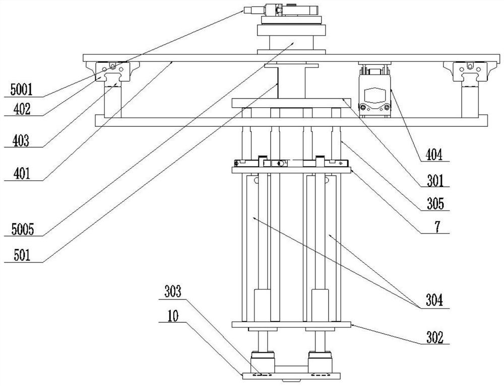
[0040] like Figure 4 , Figure 5 and Image 6 As shown, this embodiment is a further improvement made on the basis of the first embodiment. The third moving device 502 includes a swing cylinder 5001, a first timing pulley 5002 and a second timing pulley 5003 that are connected to the swing cylinder 5001 and can swing synchronously with the swing cylinder 5001. The first timing pulley 5001 is synchronized by The belt 5004 is connected with the second synchronous pulley 5003, and the second synchronous pulley 5003 is connected with the rotating shaft 501 through the bearing 5005; the rotation angle of the swing cylinder 5001 is 270°, and the first synchronous pulley 5002 is connected with the second synchronous belt The ratio of the pitch circle diameters of the wheel 5003 is 1:0.64. This is achieved by using two synchronous pulleys of different sizes, since the ratio of the pitch circle diameters of the first synchronous pulley 5002 and the second synchronous pulley 5002 is...

Embodiment 3

[0042] like Figure 7 As shown, this embodiment is a further improvement made on the basis of the first embodiment. A mounting seat 7 parallel to the bottom plate 302 is also provided on the upright column 305 between the top plate 301 and the bottom plate 302 . The mounting seat 7 is provided with a positioning device, and the positioning device includes a positioning rod 701 and a driving positioning rod 701 The fifth power device 702 that is telescopic in the vertical direction, the mounting seat 7 is connected to the positioning rod 701 through the fifth power device 702; a guide shaft 8 is also provided between the mounting seat 7 and the bottom plate 302; the fifth power device 702 for the cylinder. The positioning of the cylinder cover can be achieved.


PUM


Abstract

The invention discloses an automatic gluing device, which comprises a frame, a transmission line arranged in the frame, a translation mechanism arranged on the frame, a rotation mechanism arranged on the translation mechanism, a grasping mechanism connected with the rotation mechanism and The gluing mechanism set on the frame, the translation mechanism can slide on the frame, the grasping mechanism and the rotation mechanism can slide on the frame synchronously with the translation mechanism, and the rotation mechanism can control the rotation of the grasping mechanism, and then drive the cover Rotate, the gluing mechanism can spray glue to the cylinder cover. During the rotation of the cylinder cover, the gluing mechanism can automatically and evenly apply glue on the outside of the cylinder cover. The translation mechanism drives the rotation mechanism and the grabbing mechanism to move synchronously on the machine. The cylinder cover is moved to the top of the cartridge for assembly. The invention has the advantages of simple structure, convenient operation, high degree of automation, and improved production efficiency; it completely realizes the separation of man and machine, and reduces potential safety hazards.

Description

technical field [0001] The invention relates to the field of explosives production equipment, in particular to a cartridge cover and cartridge assembly and automatic gluing device for propellant. Background technique [0002] The propellant usually refers to the gunpowder that is installed in the chamber of the gun to fire the projectile. After being ignited by flames or sparks, it does not explode under normal conditions, but can only detonate and generate high-temperature gas rapidly, and its pressure is sufficient to launch the warhead at a certain speed, but it will not damage the chamber wall. The propellant charge module includes a cartridge, a cartridge cover and an explosive set in the cartridge. The cartridge cover and the cartridge are provided with a central hole for positioning during installation. After the cartridge cover is installed, use the corresponding sealing gasket to carry out seal. At present, the assembly of the propellant module is mainly carried o...

Claims


Application Information

Patent Timeline
Patent Type & Authority Patents(China)
IPC IPC(8): B05C5/02B05C13/02B23P19/00
CPCB05C5/0212B05C13/02B23P19/00
Inventor 李威史慧芳童卓武国梁
Owner 中国兵器装备集团自动化研究所有限公司
Why Eureka
Try Eureka