
Stamping die
A stamping die and die technology, applied in forming tools, manufacturing tools, metal processing equipment, etc., can solve the problems of die enterprise loss, high production cost, die damage, etc., and achieve high practicability, simple structure, and prevent cost increase. Effect
- Summary
- Abstract
- Description
- Claims
- Application Information
AI Technical Summary
Problems solved by technology
Method used
Image

Examples
Embodiment Construction
[0038] The drawings are schematic diagrams of the implementation of the present invention to facilitate the understanding of the operating principle of the structure. The specific product structure and proportional size can be determined according to the use environment and conventional technology.
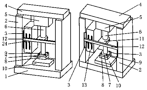
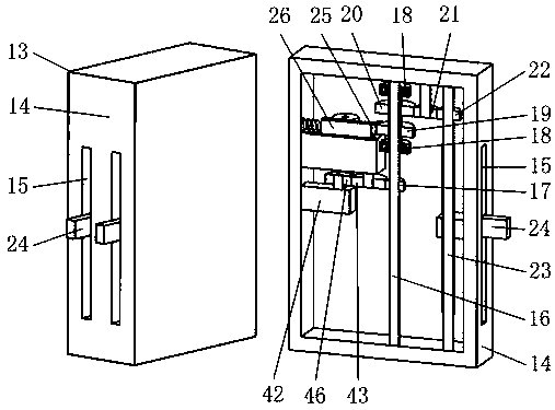
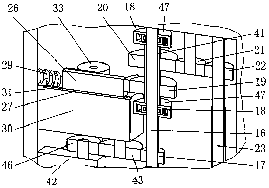
[0039] Such as figure 1 , 2 , 3, it includes base 1, support plate 2, beam 4, hydraulic pump 5, hydraulic column 6, mold base 7, lower mold 8, platform 10, limit plate 12, limit mechanism 13, such as figure 1 As shown, the beam 4 is installed on the base 1 through two supporting plates 2; the lower end of the beam 4 is installed with a hydraulic pump 5, and a hydraulic column 6 is installed under the hydraulic pump 5; the lower end of the hydraulic column 6 is installed with a mold base 7, a mold base 7. A lower mold 8 is installed below, and the lower mold 8 cooperates with the platform 10 installed on the base 1; the limit plate 12 synchronized with the expansion and contraction of ...
PUM
 Abstract
Description
Claims
Application Information