

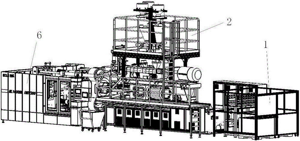
Carbon fiber forming device
A molding equipment and carbon fiber technology, which is applied in the field of carbon fiber molding equipment, can solve the problems of vulnerable carbon fiber material strength, reduced strength of finished products, and inability to make structural parts, so as to reduce shearing and heating time and avoid cost increase , the effect of long heating and shearing time
- Summary
- Abstract
- Description
- Claims
- Application Information
AI Technical Summary
Problems solved by technology
Method used
Image

Examples
Embodiment 1
[0036] Like the carbon fiber forming equipment described above, the difference in this embodiment is that the fiber feeding structure 1 is used to store the continuous fibers, and transport the continuous fibers to the feeding control structure through a hose middle.
Embodiment 2
[0038] Like the carbon fiber molding equipment described above, the difference in this embodiment is that the plastic feeding structure 2 includes a feeding scale, the feeding scale is used to measure the formula material, and the plastic feeding structure 2 The structure is provided with at least one feeding scale, each of which is used to weigh a formula material, and the plastic feeding structure sends the formula material into the feeding control structure through the bottom material opening . The feeding scale is equipped with a corresponding replenishing bin and a feeding device for realizing the functions of feeding and feeding, which facilitates continuous production, and the shape of the formula material includes granular.
Embodiment 3
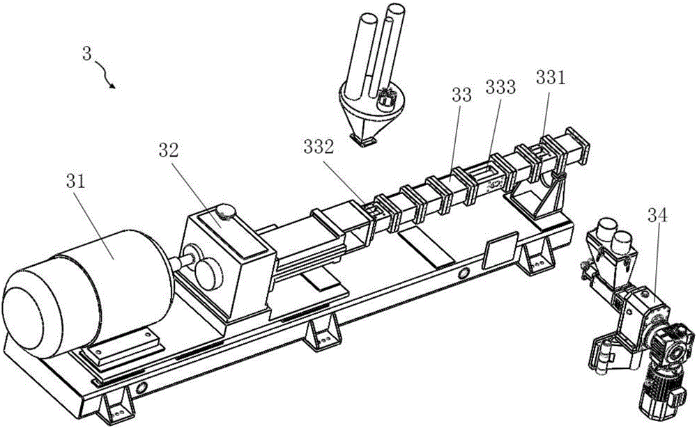
[0040] As the above-mentioned carbon fiber forming equipment, the present embodiment is different from it in that, as figure 2 As shown, the compounding structure 3 is used to shear and melt the material to be processed; the compounding structure 3 includes: a motor 31, a reducer 32, a screw assembly, and a screw barrel 33;
[0041] The motor 31 is used to provide power for the compounding process, the output shaft of the motor 31 is connected to the input end of the reducer 32, and the output end of the reducer 32 is connected to the fixed end of the screw assembly, The reducer 32 is used to drive the screw assembly to rotate around the axis; the screw assembly is composed of at least two screws arranged side by side, and at least one helix is provided on the screw, when the material to be processed When moving along the advancing direction of the helix, various forms of helixes are provided, and the combination of various forms of helixes is more conducive to the shearing...
PUM
 Abstract
Description
Claims
Application Information