Automatic machining equipment for embossing roller shaft

A technology for automatic processing and embossing rollers, which is applied in metal processing equipment, grinding/polishing equipment, and machine tools designed for grinding the rotating surface of workpieces, etc., which can solve problems such as delaying time, affecting the production efficiency of embossing rollers, and slow grinding efficiency

Inactive Publication Date: 2019-11-05
ANHUI TECHN COLLEGE OF MECHANICAL & ELECTRICAL ENG
View PDF0 Cites 3 Cited by
  • Summary
  • Abstract
  • Description
  • Claims
  • Application Information

AI Technical Summary

Problems solved by technology

[0002] At present, the printing rollers used under the existing technical conditions are usually copper rollers made of copper. This copper roller is formed by centrifugal casting of electrolytic copper. Grinding is carried out to ensure that the surface is smooth and tidy, so that it is convenient for subsequent laser engraving of printing patterns on the outer surface of the printing roller and precise assembly with the rotating shaft; the grinding efficiency of the existing grinding equipment for the printing roller is relatively slow, because the printing roller The inner and outer surfaces of the printing roller need to be polished in stages, which delays time and affects the production efficiency of the printing roller

Method used


Image

  • Automatic machining equipment for embossing roller shaft
  • Automatic machining equipment for embossing roller shaft
  • Automatic machining equipment for embossing roller shaft

Examples


Embodiment Construction

[0035] Below in conjunction with accompanying drawing and embodiment of description, specific embodiment of the present invention is described in further detail:

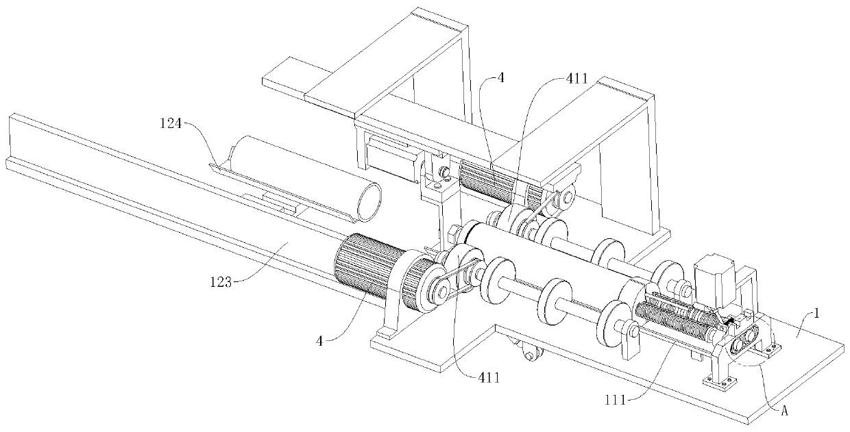
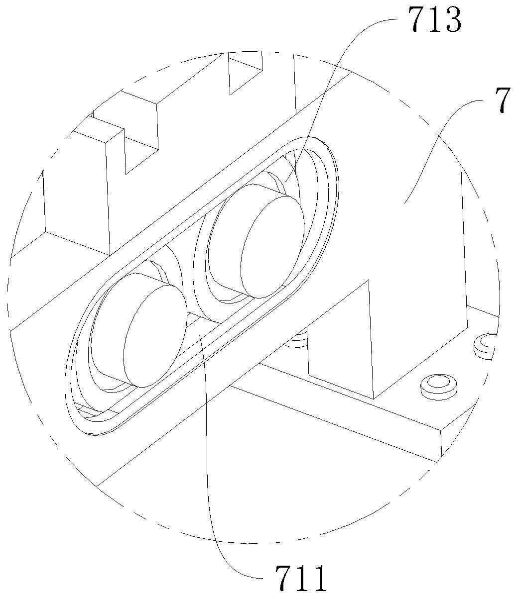
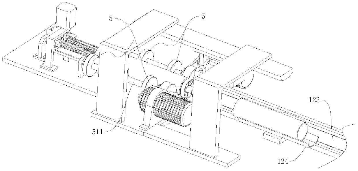
[0036] refer to Figure 1 to Figure 10The shown automatic printing roller processing equipment includes a processing table 1. The processing equipment includes a processing track 111, a contact mechanism, two outer-circle grinding mechanisms and two inner-circle grinding mechanisms. The processing track 111 is horizontally installed on the processing table 1, two outer circle grinding mechanisms are respectively arranged on one side of the processing track 111, and the upper part of the processing track 111 is provided with a propulsion electric cylinder 122, the output slider of the propulsion electric cylinder 122 faces downward, and the output slider is installed on the There is a rotating mechanism, and the contact mechanism is rotatably arranged on the output slider of the propulsion electric cylinder 122 throu...


PUM


Abstract

The invention relates to the field of embossing roller shaft machining, in particular to automatic machining equipment for an embossing roller shaft. The equipment comprises a machining table; and themachining equipment comprises a machining track, a contact mechanism, two outer circle grinding mechanisms and two inner circle grinding mechanism, wherein the machining track is horizontally arranged on the machining table, the two outer circle grinding mechanisms are arranged on the outside of one side of the machining track, a propelling electric cylinder is arranged above the machining track,a rotating mechanism is arranged on an output sliding block of the propelling electric cylinder, the contact mechanism is in transmission connection with the rotating mechanism, the end, facing the contact mechanism, of the machining track is an upstream end, a supporting device is arranged at a downstream end of the machining track, the two inner circle grinding mechanisms are symmetrically arranged between the two outer circle grinding mechanisms and are connected with the supporting device through a micro-motion adjuster, a discharging device is further arranged between the supporting device and each inner circle grinding mechanism, and the discharging devices can movably sleeve the micro-motion adjuster. According to the equipment, the inner and outer surfaces of the embossing rollershaft can be ground simultaneously, so that the machining efficiency is greatly improved.

Description

technical field [0001] The invention relates to the field of printing roller processing, in particular to an automatic processing equipment for printing rollers. Background technique [0002] At present, the printing rollers used under the existing technical conditions are usually copper rollers made of copper. This copper roller is formed by centrifugal casting of electrolytic copper. Grinding is carried out to ensure that the surface is smooth and tidy, so that it is convenient for subsequent laser engraving of printing patterns on the outer surface of the printing roller and precise assembly with the rotating shaft; the grinding efficiency of the existing grinding equipment for the printing roller is relatively slow, because the printing roller The inner and outer surfaces of the roller need to be polished in stages, which delays time and affects the production efficiency of the printing roller. Contents of the invention [0003] The object of the present invention is ...

Claims


Application Information

Patent Timeline
Patent Type & Authority Applications(China)
IPC IPC(8): B24B5/12B24B27/00B24B41/00B24B41/06B24B47/12B24B47/20B24B47/22
CPCB24B5/12B24B27/0023B24B27/0069B24B27/0076B24B41/005B24B41/067B24B47/12B24B47/20B24B47/22
Inventor 方慧敏赵钢胡如方耿慧莲赵文英朱稚华高雄齐浩
Owner ANHUI TECHN COLLEGE OF MECHANICAL & ELECTRICAL ENG
Why Eureka
Try Eureka