
Connection structure of sensor and motor bicycle

A technology for assisting bicycles and connecting structures, applied in bicycle frames, bicycle accessories, crank structures, etc., can solve problems such as life reduction, inaccurate torque measurement, sensor zero-point drift, etc., to improve the experience, avoid bad impact, and protect the sensor. Effect

Pending Publication Date: 2019-11-05
SHANGHAI MINDENG IND TECH CO LTD
View PDF0 Cites 1 Cited by
  • Summary
  • Abstract
  • Description
  • Claims
  • Application Information

AI Technical Summary

Problems solved by technology

The main disadvantage of the rear axle dropout sensor method is that the torque measurement is inaccurate and seriously affected by external interference. In this method, the sensor is built into the metal member at the connection between the chainstay and the chainstay. This position is at the key part of the rear axle support. , the force is large and complex, which has a negative impact on accuracy and life. If the rear wheel maintenance is disassembled, it will cause a large zero-point drift of the sensor or even mechanical damage; in addition, the pedaling force is transmitted from the pedal to the rear fork , the path is relatively long, and the existence of the elastic body causes the rear axle dropout sensor to have disadvantages in terms of response time and accuracy
[0004] The boom-type bottom bracket method is to install a pressure sensor between the bottom bracket and the frame. The bottom bracket and the sensor are kept in contact and generate pressure through the restraint of the chain, so that the sensor can monitor the riding strength of the rider. However, this There are still several problems that have not been resolved
[0005] Since the bottom bracket is only hinged on the frame and has a pure contact relationship with the pressure sensor, the bottom bracket is not in a stable state. In actual riding, due to the limitations of road conditions and various riding conditions, the chain cannot Completely restrict the activities of the bottom bracket, and the bottom bracket is in a random swing state, resulting in frequent collisions with the pressure sensor, which not only leads to poor riding experience, but also causes considerable damage to the pressure sensor, or shortens the life of the pressure sensor;
[0006] The sensor can only sense pressure, not tension, so it cannot sense downhill or brake;
[0007] The sensor only accepts one-way pressure, resulting in incomplete stress release of the elastic body, resulting in serious sensor zero-point drift. In fact, most of the sensors of power-assisted bicycles on the market currently have a certain degree of zero-point drift, so every time you start it. Perform zero point correction, the experience is not good;
[0008] The integral bottom bracket structure is complicated, the processing technology is complicated, the installation is difficult and the cost is high;
[0009] In the complete vehicle state, the bottom bracket boom usually needs to form a certain angle (for example, 90 degrees) with respect to the horizontal plane to obtain the optimal power assist effect. It will lead to the change of the included angle, and it will not be possible to achieve the predetermined included angle through simple installation and adjustment to realize the expected function;
[0010] The limit pressure that the pressure sensor can accept is limited, and usually cannot exceed 50% of the sensor's range. At the same time, in order to ensure the measurement accuracy, the sensor's range should not be too large. However, the pressure of the bottom bracket on the sensor depends on the weight and strength of the rider. And the range is very wide, so under normal technical conditions, in order to achieve higher accuracy, the pressure sensor has a great risk of overload but lacks the necessary protection measures. Most of the sensors of power-assisted bicycles on the market do not have effective overload protection. means

Method used


Image

  • Connection structure of sensor and motor bicycle
  • Connection structure of sensor and motor bicycle
  • Connection structure of sensor and motor bicycle

Examples


Embodiment Construction

[0041] In order to make the purpose, technical solution and advantages of the present invention clearer, the technical solution of the present invention will be further described below.

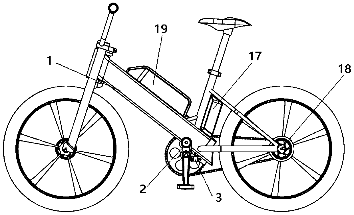
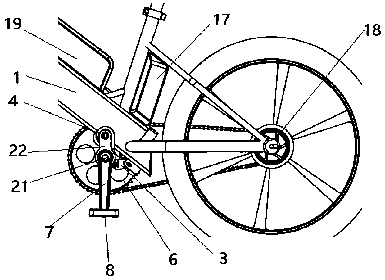
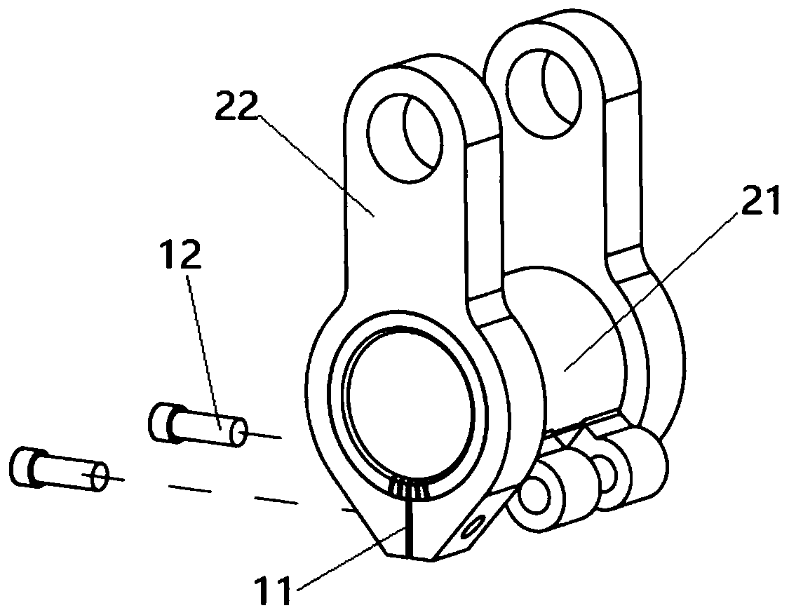
[0042] Such as figure 1 with figure 2 As shown, the present invention proposes a connection structure between a sensor and a power-assisted bicycle, comprising a vehicle frame 1, a bottom bracket assembly 2 and a sensor 3; the bottom bracket assembly 2 is hinged with the vehicle frame 1 through a rotating shaft 4; Hinged to each other, the other end of the sensor 3 is hinged to the frame 1; the sensor 3, the frame 1 and the bottom bracket assembly 2 form a stable triangular structure; the stability of the bottom bracket 21 is strengthened, and the bottom bracket assembly is avoided during the riding process of the vehicle. 21 Various adverse impacts on the sensor 3. On the other hand, the sensor 3 can be randomly subjected to tension or pressure during riding, which avoids the incomplete rele...


PUM


Abstract

The invention provides a connection structure of a sensor and a motor bicycle. The connection structure comprises a frame, a five-way component and a sensor, wherein the five-way component is articulated with the frame through a rotating shaft; one end of the sensor is mutually articulated with the five-way component; the other end of the sensor is mutually articulated with the frame; the stable triangular structure is formed by the sensor, the frame and the five-way component; a middle axle is arranged in the five-way component; a chain wheel is arranged on the middle axle in a sleeving manner and is in driving connection with a rear wheel through a chain; cranks are arranged at the two ends of the middle axle; and pedals are arranged at the bottom ends of the cranks. The provided connection structure of the sensor and the motor bicycle has a simple installation structure, can effectively protect the sensor and has accurate perception.

Description

technical field [0001] The invention relates to the technical field of bicycles, in particular to a connection structure between a sensor and a power-assisted bicycle. Background technique [0002] Electric power-assisted bicycles usually use torque sensors or torque measurement methods (TMM) to realize real-time monitoring of the rider's pedaling strength and combine the pedaling frequency data to adjust the power output to achieve the purpose of riding assistance. The traditional torque sensor is located in the rotating part, the structure is too complex, the reliability is poor, and the maintainability is poor. Most of them are customized structures, which lack versatility. Moreover, due to the elastic body under the action of a single external force, it is easy to cause incomplete stress release, which leads to sensor failure. Zero drift, and can not sense the slope, can not sense the brakes, and lacks effective mechanical overload protection measures. [0003] At prese...

Claims


Application Information

Patent Timeline
Patent Type & Authority Applications(China)
IPC IPC(8): B62M6/50B62M3/00B62K19/30
CPCB62M6/50B62M3/00B62K19/30
Inventor 梁德
Owner SHANGHAI MINDENG IND TECH CO LTD
Learn More