Hydraulic lifting jack

A hydraulic lifting and jacking technology, which is applied in the direction of lifting devices, etc., can solve the problems of unsuitable for off-road vehicles, high lifting height, and limited lifting height of jacks, etc., and achieve the effect of convenient operation, strong adaptability, and improved lifting height

Pending Publication Date: 2019-11-05
HAIYAN AIHUA MACHINERY CO LTD
View PDF0 Cites 2 Cited by
  • Summary
  • Abstract
  • Description
  • Claims
  • Application Information

AI Technical Summary

Problems solved by technology

The vehicle-mounted hydraulic jack in the prior art can only perform two-stage lifting on the basis of the original height, and it is no problem for ordinary family cars to use, but it is not suitable for off-road vehicles due to the high chassis of off-road vehicles
The lifting height of the jack in the prior art is limited by the original height, which cannot meet the requirements of low original height and high lifting height

Method used


Image

  • Hydraulic lifting jack
  • Hydraulic lifting jack
  • Hydraulic lifting jack

Examples


Embodiment Construction

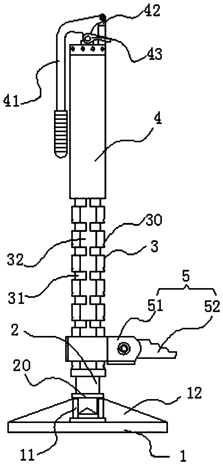
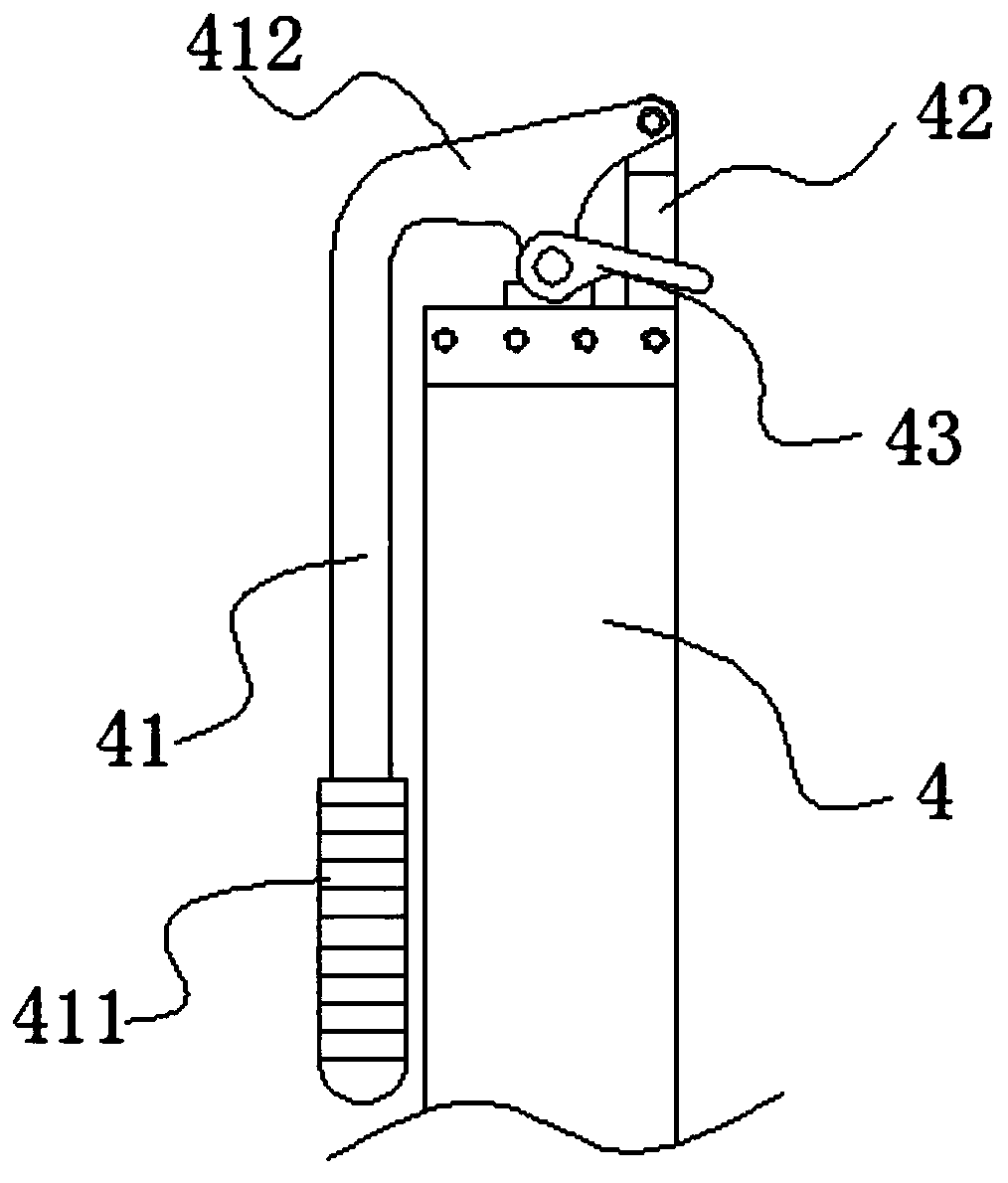
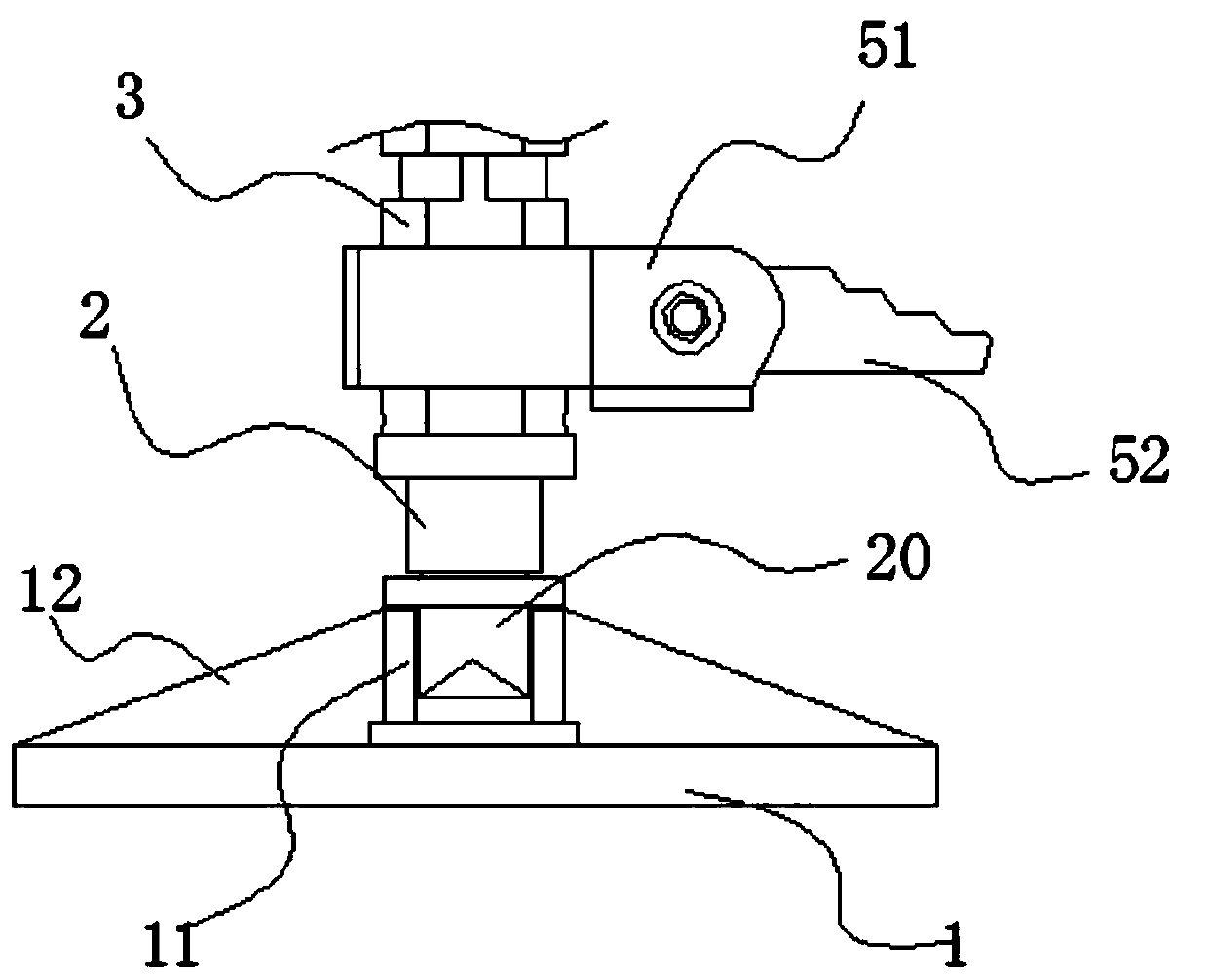
[0020] refer to Figure 1 to Figure 7 A hydraulic lifting jack of the present invention comprises a base 1, a lower cavity tube 2, an outer casing 3, a hydraulic cylinder 4, and a lifting assembly 5 sleeved on the outer casing 3 arranged sequentially from bottom to top, and the lower cavity tube 2 The lower end of the lower chamber tube 2 is connected to the base 1, the upper end of the lower cavity pipe 2 runs through the inner cavity of the outer casing 3, and is connected with the piston rod of the hydraulic cylinder 4, and the upper end of the outer casing 3 is threadedly connected with the lower end of the cylinder body of the hydraulic cylinder 4, The top of the hydraulic cylinder 4 is installed with a pressure rod 41 to control the elongation of the lower cavity tube 2, and a plurality of limit ring grooves 31 are spaced apart on the outer sleeve 3 along its axial direction, and the lifting assembly 5 includes a support leg A sleeve 51 and a support body 52, the support...


PUM


Abstract

The invention provides a hydraulic lifting jack. The hydraulic lifting jack comprises a base, a lower cavity tube, an outer sleeve pipe, a hydraulic cylinder and a lifting assembly which are sequentially arranged from bottom to top, wherein the lifting assembly sleeves the outer sleeve pipe. The lower end of the lower cavity tube is connected with the base, the upper end of the lower cavity tube penetrates through an inner cavity of the outer sleeve pipe and is connected with a piston rod of the hydraulic cylinder, and a pressing rod for controlling the lower cavity tube to extend is installedon the top of the hydraulic cylinder. A plurality of limiting annular grooves are formed in the outer sleeve pipe at intervals in the axis direction of the outer sleeve pipe. The lifting assembly comprises a leg supporting cover and a supporting body, the leg supporting cover sleeves the outer sleeve pipe, locking protruding parts are symmetrically arranged on an inner ring of the leg supportingcover, and the limiting annular grooves abut against and cooperate with the lower end faces of the locking protruding parts to support the leg supporting cover and preventing the leg supporting coverfrom sliding. Single-side grooves are symmetrically formed in the outer wall of the outer sleeve pipe, and adjusting areas which do not interfere with vertical sliding of the locking protruding partsare arranged between the single-side grooves and the inner ring of the leg supporting cover. The hydraulic lifting jack is adjustable in height, high in adaptability and capable of meeting requirements of various vehicle types.

Description

【Technical field】 [0001] The invention relates to the technical field of jacks, in particular to a hydraulic lifting jack. 【Background technique】 [0002] The car jack is placed in the toolbox of the car and is used to lift the body when replacing the spare tire. The car jack includes pneumatic jacks, electric jacks, hydraulic jacks and mechanical jacks. Hydraulic jacks and mechanical jacks are commonly used. The vehicle-mounted hydraulic jack in the prior art can only be lifted in two stages on the basis of the original height, and there is no problem in the use of general family cars, but it is not suitable for off-road vehicles because the chassis of off-road vehicles is relatively high. The lifting height of the jack in the prior art is limited by the original height, which cannot meet the requirement of low original height and high lifting height. A kind of hydraulic lifting jack is proposed now. 【Content of invention】 [0003] The object of the present invention is...

Claims


Application Information

Patent Timeline
IPC IPC(8): B66F3/25B66F3/28
CPCB66F3/25B66F3/28
Inventor 金爱玉金严斌
Owner HAIYAN AIHUA MACHINERY CO LTD
Why Eureka
Try Eureka