A rotary drilling rig power head buffer device

A technology for buffer devices and rotary drilling rigs, which is applied to rotary drilling rigs, rotary drilling, and non-rotational vibration suppression. It can solve the problems of short life and harsh working environment of springs, and achieve the goal of prolonging the service life and improving the working environment. Effect

Active Publication Date: 2020-11-27
盐城中威机械有限公司
View PDF4 Cites 0 Cited by
  • Summary
  • Abstract
  • Description
  • Claims
  • Application Information

AI Technical Summary

Problems solved by technology

[0005] For example, the cushioning device of the above-mentioned patent document adopts (helical) spring external (on the sleeve) to realize the buffer between the sleeve and the upper platen. The working environment of the spring in this way is quite harsh and the service life is short needs to be improved

Method used


Image

  • A rotary drilling rig power head buffer device
  • A rotary drilling rig power head buffer device
  • A rotary drilling rig power head buffer device

Examples


Embodiment Construction

[0020] In order to describe the technical content, structural features, goals and effects of the present invention in detail, the following examples are given to describe the embodiments in conjunction with the accompanying drawings.

[0021] In describing the present invention, it is to be understood that the terms "central", "longitudinal", "transverse", "front", "rear", "left", "right", "vertical", "horizontal", The orientations or positional relationships indicated by "top", "bottom", "inner", "outer", etc. are based on the orientations or positional relationships shown in the drawings, and are only for the convenience of describing the present invention and simplifying the description, rather than indicating or implying The devices or elements referred to must have a specific orientation, be constructed and operate in a specific orientation, and therefore should not be construed as limiting the scope of the invention.

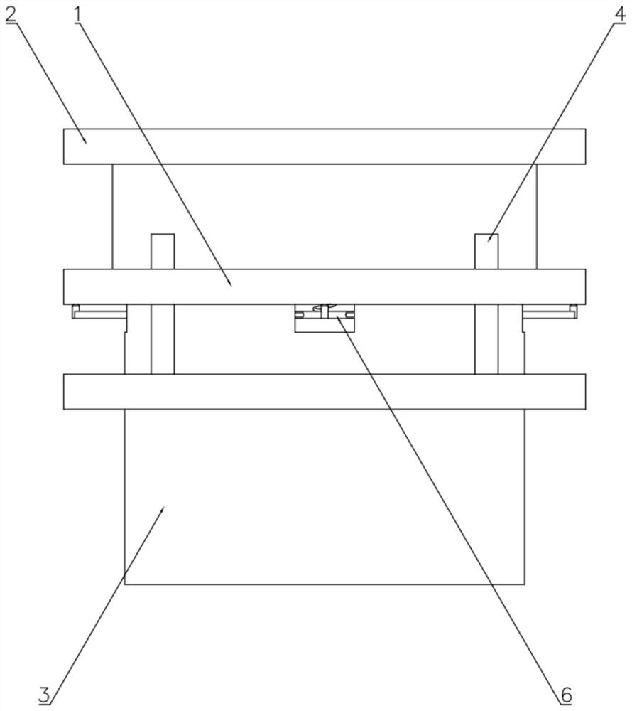
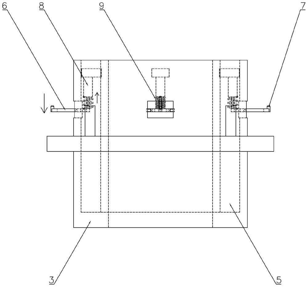
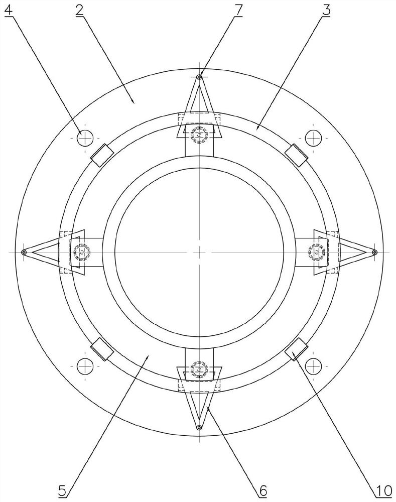
[0022] The invention provides a power head buffer de...


PUM


Abstract

The invention provides a rotary drilling rig power head buffering device. An upper pressing disc with a bottom flange, a sleeve which is in sliding connection with the bottom flange, and a guide rod guiding the upper pressing disc to slide up and down are included. The sleeve is a hollow structure with an annular cavity. The annular cavity is rotationally connected with levers swinging up and down. The multiple levers are included and evenly distributed in the circumferential direction of the sleeve. The levers extend out of the annular cavity, and supporting ends are formed. The sleeve is provided with through holes for the levers to stretch out. The supporting ends abut against the bottom flange. The ends, in the annular cavity, of the levers are connected with shock absorbers. The shockabsorbers are fixed in the annular cavity, and the shock absorbers are sleeved with spiral springs. The faces, which are in sliding connection with the bottom flange, of the sleeve are provided withlimiting keys, the positions, corresponding to the limiting keys, of the bottom flange are provided with limiting grooves, a good work environment can be provided for the springs, and accordingly theservice life of the whole buffering device is prolonged.

Description

technical field [0001] The invention relates to the technical field of buffering of a power head of a rotary drilling rig, in particular to a buffering device for a power head of a rotary drilling rig. Background technique [0002] Rotary drilling rig is a construction machine suitable for hole-forming operations in building foundation engineering. It is mainly suitable for the construction of sandy soil, cohesive soil, silty soil and other soil layers. It is widely used in various foundation constructions such as cast-in-place piles, diaphragm walls, and foundation reinforcement. The rated power of rotary drilling rigs is generally 125-450kW. The output torque is 120-400kN m, the maximum hole diameter can reach 1.5-4m, and the maximum hole depth is 60-90m, which can meet the requirements of various large-scale foundation construction. [0003] The power head is an important part of the rotary drilling rig, usually including a power box, a reducer and a buffer device. The ...

Claims


Application Information

Patent Timeline
Patent Type & Authority Patents(China)
IPC IPC(8): E21B3/02F16F15/02
CPCE21B3/02F16F15/022F16F2238/026
Inventor 黄永中
Owner 盐城中威机械有限公司
Why Eureka
Try Eureka