Movable combustion furnace structure

A combustion furnace, mobile technology, applied in the direction of combustion method, combustion type, incinerator, etc., can solve the problems of low combustion efficiency, incomplete combustion, easy smoldering, etc., achieve high combustion efficiency, avoid smoldering, and not easy to smolder burning effect

Inactive Publication Date: 2019-11-05
AETHER PRECISION TECH INC
View PDF4 Cites 0 Cited by
  • Summary
  • Abstract
  • Description
  • Claims
  • Application Information

AI Technical Summary

Problems solved by technology

However, most of the existing combustion furnaces have problems such as easy smoldering, incomplete combustion and low combustion efficiency, and fly ash is easy to float out during combustion, which is prone to pollution problems

Method used


Image

  • Movable combustion furnace structure
  • Movable combustion furnace structure
  • Movable combustion furnace structure

Examples


no. 1 example

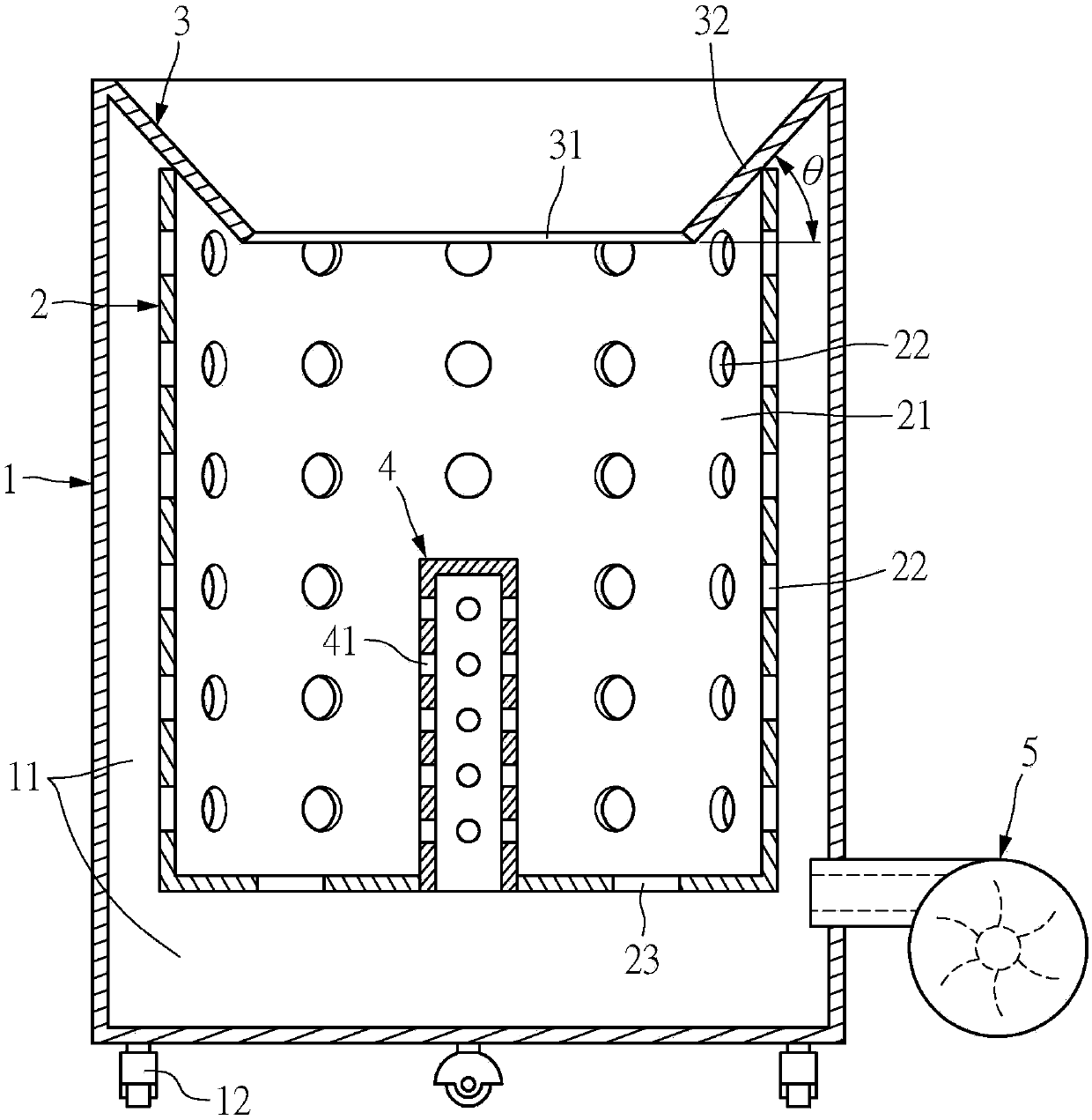
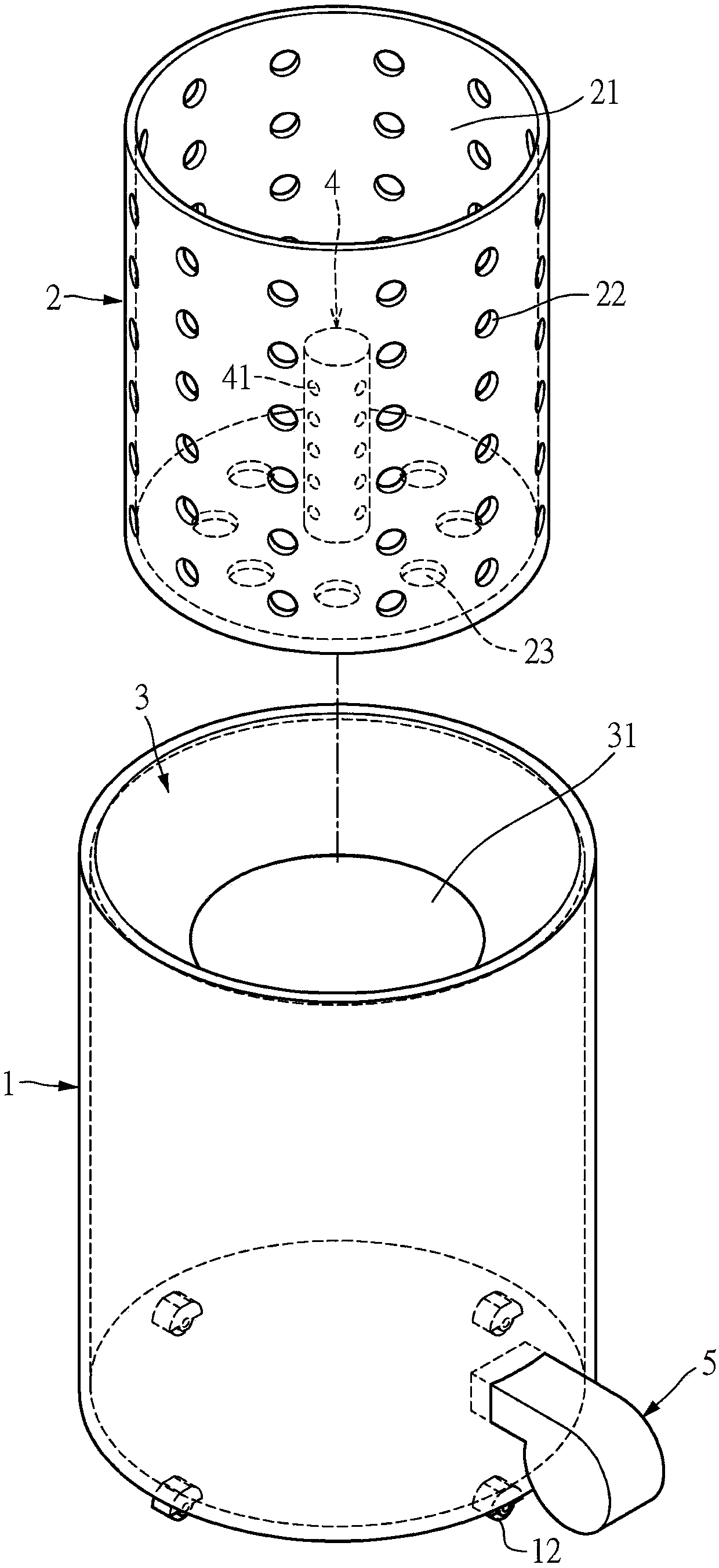
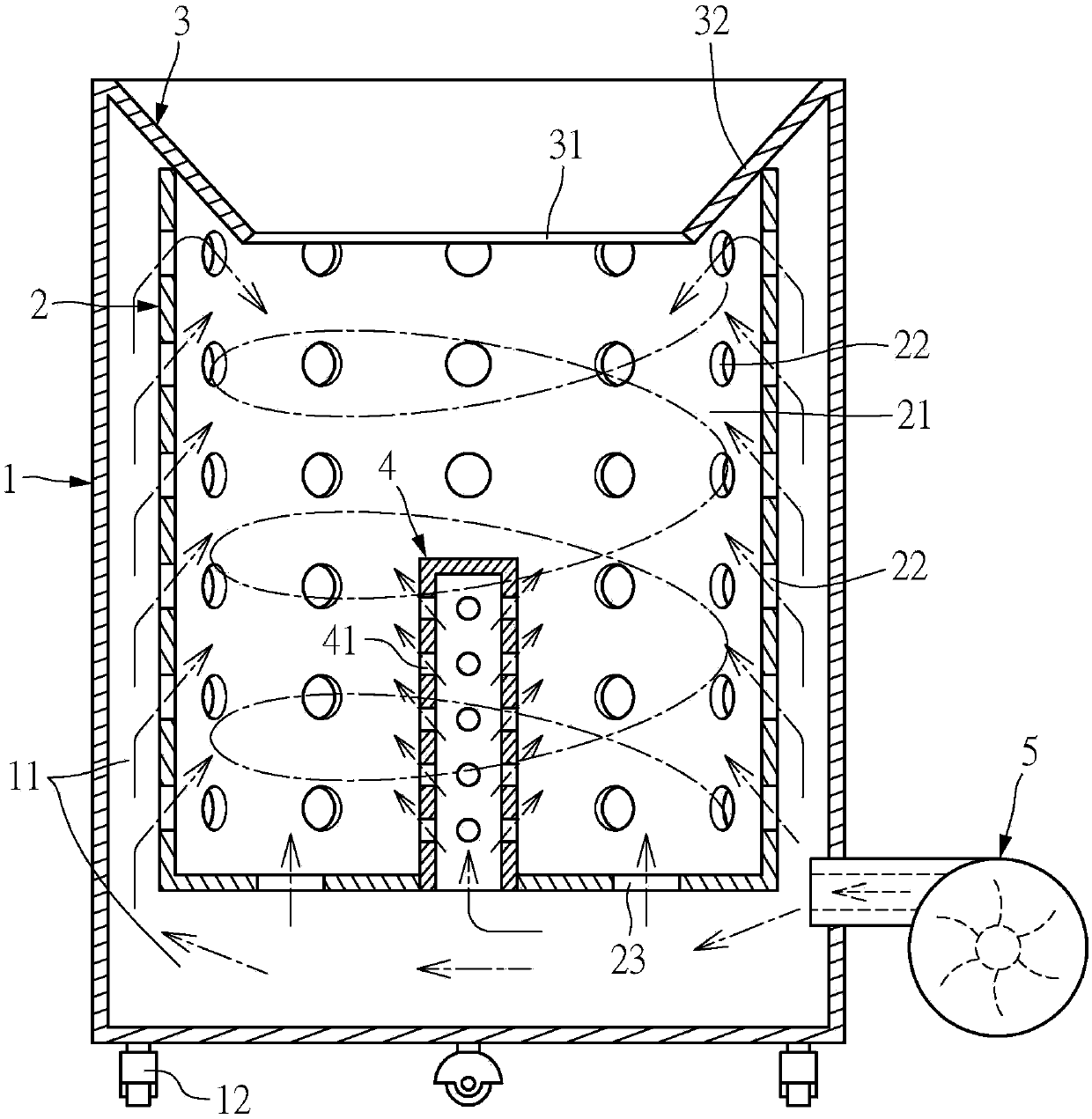
[0030] see figure 1 and figure 2 , The present invention provides a mobile combustion furnace structure, including an outer furnace body 1, an inner furnace body 2, a beveled flange 3, at least one flame-supporting tube 4 and a blower 5.

[0031] The outer furnace body 1 and the inner furnace body 2 are preferably made of metal or ceramic materials. The outer furnace body 1 and the inner furnace body 2 are hollow bodies, preferably hollow cylinders, but the outer furnace body 1 and the inner furnace body The shape and size of the body 2 are not limited. In this embodiment, the inner furnace body 2 is a hollow cylinder with an inner diameter of 310mm, 360mm, 450mm, 470mm, 800mm or 880mm. The inner furnace body 2 is arranged inside the outer furnace body 1, and an interval is formed between the outer furnace body 1 and the inner furnace body 2, that is, the side wall of the inner furnace body 2 and the bottom of the inner furnace body 2 and the outer furnace body 1 An air pas...

no. 2 example

[0041] see Figure 5 and Figure 6 , in the present embodiment, the bottom of this inner furnace body 2 also can have a row of ash opening 24, and the bottom of this inner furnace body 2 is pivotally provided with a sliding hopper 7, that is, one side of the sliding hopper 7 is hinged with a rotating shaft and hinged. The pivot assembly 25 is pivotally arranged at the bottom of the inner furnace body 2, so that the sliding hopper 7 can swing downward to open the ash discharge port 24 or swing upward to close the ash discharge port 24. When the sliding hopper 7 swings upwards to close the ash discharge port 24, it can be fixed by a fixing member 71, which can be various existing fixing members such as screws, latches or tenons. When the sliding hopper 7 swings downwards to open the ash discharge port 24, the sliding hopper 7 can be inclined to guide the ashes in the combustion chamber 21 to be discharged outwards to facilitate ash removal.

[0042] In addition, a door panel 1...

no. 3 example

[0044] see Figure 7 , in this embodiment, further, a vertical wall 33 is provided around the bottom of the flange opening 31, and the vertical wall 33 can be formed by the vertical downward extension of the lower end of the annular sloping plate 32, utilizing the vertical wall 33 Design, can more effectively avoid fly ash flying out when burning, not easy to produce pollution.


PUM

PropertyMeasurementUnit
Apertureaaaaaaaaaa
Apertureaaaaaaaaaa

Abstract

The invention provides a movable combustion furnace structure. The movable combustion furnace structure comprises an outer furnace body, an inner furnace body, an inclined flange, at least one flame-assisting tube and an air blower. An air channel is formed between the side walls and the bottom of the inner furnace body and the outer furnace body, and a combustion chamber is formed in the inner furnace body; and the side wall and the bottom of the inner furnace body are provided with first air inlets and second air inlets respectively, and the first air inlets and the second air inlets communicate with the air channel. The inclined flange is arranged at the top of the outer furnace body and the top of the inner furnace body and exposed outside; and a flange contractive opening is formed inthe lower end of the inclined flange. The flame-assisting tube is erected in the combustion chamber of the inner furnace body and is provided with a plurality of holes, and the interior of the flame-assisting tube communicates with the air channel. The air blower communicates with the air channel, and the air blower communicates with the first air inlets, the second air inlets and the holes through the air channel. Therefore, the movable combustion furnace structure has the effects of being not prone to smolder, complete in combustion, high in combustion efficiency and the like.

Description

technical field [0001] The invention relates to a combustion furnace structure, in particular to a mobile combustion furnace structure capable of burning combustibles. Background technique [0002] The combustion furnace can be used to burn combustibles. The furnace body of the existing combustion furnace has a combustion chamber, and combustibles (such as gold paper, branches, leaves and papers, etc.) can be put into the combustion chamber through the feeding port for combustion. However, most of the existing combustion furnaces have the problems of easy smoldering, incomplete combustion and low combustion efficiency, and fly ash is easy to float out during combustion, which is easy to cause pollution. Contents of the invention [0003] The technical problem to be solved by the present invention is to provide a mobile combustion furnace structure, which has the effects of not easy to smolder, complete combustion and high combustion efficiency, and can avoid fly ash flying...

Claims


Application Information

Patent Timeline
IPC IPC(8): F23G5/40F23G5/44
CPCF23G5/40F23G5/44F23G2203/60
Inventor 宋志云蔡怀方徐仪如
Owner AETHER PRECISION TECH INC
Why Eureka
Try Eureka