Grounding impedance tester

A grounding impedance and tester technology, applied in grounding resistance measurement, measuring resistance/reactance/impedance, instruments, etc., can solve the problems of cumbersome, multi-operation measuring tools, increasing measurement burden, etc., to simplify measurement operations and improve calculation accuracy , The effect of reducing the measurement burden

Pending Publication Date: 2019-11-05
武汉市康达电气有限公司
View PDF0 Cites 0 Cited by
  • Summary
  • Abstract
  • Description
  • Claims
  • Application Information

AI Technical Summary

Problems solved by technology

[0006] In order to solve the problem that when using the power frequency high current method combined with the phase inversion method to test the grounding impedance, many measu

Method used


Image

  • Grounding impedance tester
  • Grounding impedance tester
  • Grounding impedance tester

Examples


Embodiment 1

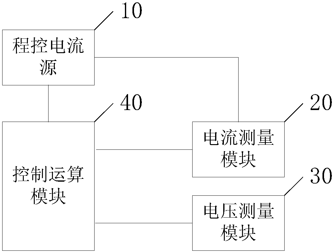
[0046] An embodiment of the present invention provides a grounding impedance tester, see figure 2 , the grounding impedance tester includes a programmable current source 10 , a current measurement module 20 , a voltage measurement module 30 and a control operation module 40 . Wherein, the input end of the program-controlled current source 10 is electrically connected to the earth (i.e., the ground grid under test), the output end of the program-controlled current source 10 is electrically connected to the input end of the current measurement module 20, and the output end of the current measurement module 20 is respectively connected to the earth and The control operation module 40 is electrically connected, the input end of the voltage measurement module 30 is electrically connected to the earth, the output end of the voltage measurement module 30 is electrically connected to the earth and the control operation module 40 respectively, and the control operation module 40 is ele...

Embodiment 2

[0055] Embodiments of the present invention will combine Figure 4 and Figure 5 , detail figure 2 A preferred structure of the ground impedance tester shown.

[0056] see Figure 4 , the control operation module 40 includes a zero-crossing shaping unit 401 and a control unit 402 . The input end of the zero-crossing shaping unit 401 is electrically connected to the output end of the voltage measurement module 30, the output end of the zero-crossing shaping unit 401 is electrically connected to the input end of the control unit 402, and the input end of the control unit 402 is also connected to the current measurement module 20 respectively. The output end of the control unit 402 is electrically connected to the output end of the voltage measurement module 30 , and the output end of the control unit 402 is electrically connected to the control end of the programmable current source 10 .

[0057] The zero-crossing shaping unit 401 is used to convert the ground disturbance v...


PUM


Abstract

The invention discloses a grounding impedance tester, and belongs to the impedance measuring technology field. The grounding impedance tester comprises a program-controlled current source, a current measuring module, a voltage measuring module, and a control calculation module. The current source is used to apply the incremental testing current to a tested grounding network. The current measuringmodule is used to measure the incremental testing current. The voltage measuring module is used to measure a ground interference voltage generated by the measured ground interference current on the grounding impedance of the tested grounded network. The synthesized voltage generated by the synthesized current of the ground interference current and the incremental test current on the grounding impedance can be measured. The control calculation module is used to control the program-controlled current source to output the increment test current, the frequency and the phase of which are the same as that of the tested grounding network according to the measured ground interference voltage signal. According to the measured incremental test current and the measured ground interference voltage andthe synthesized voltage, the grounding impedance is calculated.

Description

technical field [0001] The invention relates to the technical field of impedance measurement, in particular to a grounding impedance tester. Background technique [0002] At present, the three-pole method is commonly used to measure the power frequency grounding impedance of large-scale grounding grids such as substations and power plants. Such as figure 1 As shown, a test current I is applied between the current electrode C and the ground grid G ​​under test through a constant current source I m , test current I m It flows out from the terminal button of current source C1, connects to the current pole C through the test line, enters the ground, returns to the ground network through the earth, and then connects the return point B of the ground network to the terminal button of the current source C2 through the test line to form a current loop. The voltmeter V measures the test current I m The voltage Up generated between the voltage pole P and the ground grid; one termin...

Claims


Application Information

Patent Timeline
IPC IPC(8): G01R27/20G01R27/08
CPCG01R27/08G01R27/205
Inventor 胡晓晖
Owner 武汉市康达电气有限公司
Why Eureka
Try Eureka