A decision-making method for machining step sequence of multi-cavity structural parts based on transition feature simplification

A technology of feature simplification and decision-making method, which is applied in the direction of program control, comprehensive factory control, electrical program control, etc., can solve the problems of low intelligence, no consideration of the influence of transition features, and the scrapping of processed parts to achieve the effect of meeting actual needs

Active Publication Date: 2021-09-21
TAIYUAN UNIV OF TECH
View PDF2 Cites 0 Cited by
  • Summary
  • Abstract
  • Description
  • Claims
  • Application Information

AI Technical Summary

Problems solved by technology

These algorithms mainly have the following problems: (1) The processing feature distance depends on manual calculation
The manual calculation result is used as the parameter input of the optimization algorithm, not only the degree of intelligence is low, but also it is difficult to guarantee the accuracy of the calculation result; (2) The influence of the transition feature on the tool path planning is not considered
Transition features widely exist at the corners of the cavity, and the NC machining of transition features on the outer contour of the cavity can be realized by simply modifying the tool offset parameters; while machining the inner contour, an auxiliary transition circle must be artificially added by the programmer arc, and it must be ensured that the radius of the transition arc is greater than the radius of the tool, which not only increases the difficulty of NC programming, but also slightly negligent, when the radius of the transition arc is smaller than the radius of the tool, overcutting will occur due to tool interference, and the processed parts will be scrapped

Method used


Image

  • A decision-making method for machining step sequence of multi-cavity structural parts based on transition feature simplification
  • A decision-making method for machining step sequence of multi-cavity structural parts based on transition feature simplification
  • A decision-making method for machining step sequence of multi-cavity structural parts based on transition feature simplification

Examples


Embodiment Construction

[0027] The technical solutions of the present invention will be further described in more detail below in conjunction with specific embodiments. Apparently, the described embodiments are only some of the embodiments of the present invention, not all of them. Based on the embodiments of the present invention, all other embodiments obtained by persons of ordinary skill in the art without making creative efforts shall fall within the protection scope of the present invention.

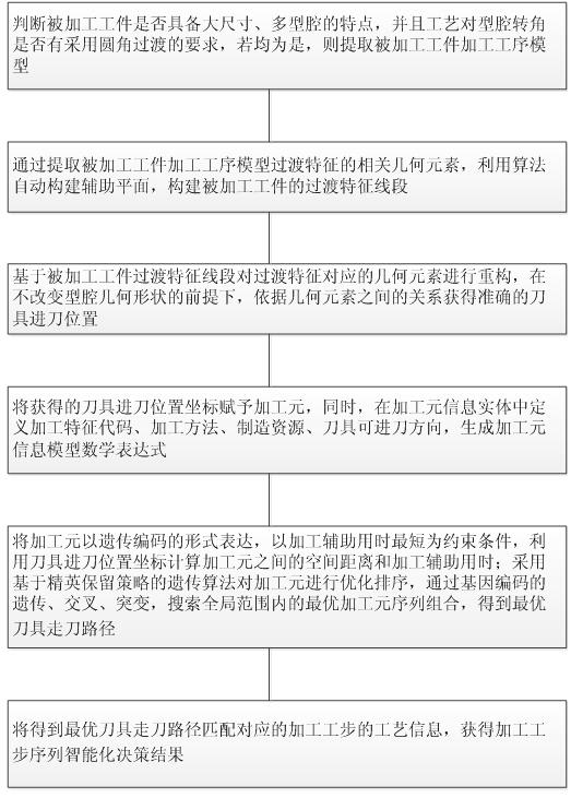
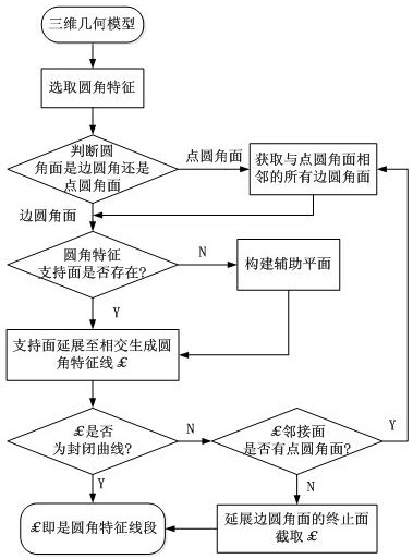
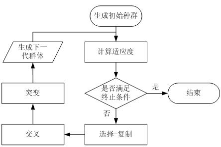
[0028] In order to eliminate the interference of the arc transition surface on the tool path planning, the present invention proposes a transition feature simplification algorithm, which can simplify the transition feature and obtain the tool entry position without modifying the design model. On this basis, combined with the processing element to calculate the spatial position distance between different cavities, the improved genetic algorithm is used to calculate the processing auxiliary time of different...


PUM


Abstract

The invention discloses a multi-cavity structural part processing step sequence decision-making method based on transition feature simplification, which sequentially includes: judging the characteristics of the processed workpiece and the cavity corner requirements, and extracting the processing procedure model of the processed part from the three-dimensional processing technology design system ;By extracting the relevant geometric elements of the transition feature, the algorithm is used to automatically construct the auxiliary plane and the transition feature line segment; based on the transition feature line segment, the geometric elements corresponding to the transition feature are reconstructed, and the accurate tool feed is obtained according to the relationship between the geometric elements position; assign the obtained tool feed position coordinates to the processing element, and define the process information in the processing element information entity to generate the mathematical expression of the processing element information model; use the genetic algorithm of the elite retention strategy to optimize the sorting of the processing elements, and obtain the most Optimal tool path; eventually, the process information of the optimal tool path matching the corresponding processing step will be obtained, and the intelligent decision-making result of the processing step sequence will be obtained.

Description

technical field [0001] The invention belongs to the technical field of digital processing, and relates to a processing step decision method, in particular to a multi-cavity structural part processing step sequence decision method based on transition feature simplification. Background technique [0002] Cavity is a common structure in aircraft structural parts and mold design. In actual production and manufacturing, it is usually processed by CNC milling. Large-size multi-cavity parts have a large overall outline size (the overall size of the aircraft structure can reach 4000mm×2000mm), a large number of cavities and a long distance from each other. An important factor that cannot be ignored in the decision-making process. The process planning of multi-cavity parts needs to consider the cavity contour and its spatial position relationship. In the case of keeping the cutting method unchanged, the number of tool changes and idle strokes should be reduced as much as possible. ...

Claims


Application Information

Patent Timeline
Patent Type & Authority Patents(China)
IPC IPC(8): G05B19/19
CPCG05B19/19G05B2219/35166Y02P90/02
Inventor 辛宇鹏武锋锋杨胜强李文辉李元恒
Owner TAIYUAN UNIV OF TECH
Why Eureka
Try Eureka