Reception device and communication system

A technology for receiving devices and communication lines, applied in baseband systems, transmission systems, digital transmission systems, etc., can solve the problems of noise in communication lines, failure of normal communication, and large capacitance between lines, and achieve the effect of improving noise immunity

Active Publication Date: 2019-11-05
MITSUBISHI ELECTRIC CORP
View PDF4 Cites 0 Cited by
  • Summary
  • Abstract
  • Description
  • Claims
  • Application Information

AI Technical Summary

Problems solved by technology

[0003] Here, when the 3-core cable is long (for example, 100m or more), the inter-line capacitance increases, noise occurs in the communication line, and normal communication may not be possible.

Method used


Image

  • Reception device and communication system
  • Reception device and communication system
  • Reception device and communication system

Examples


Embodiment approach 1

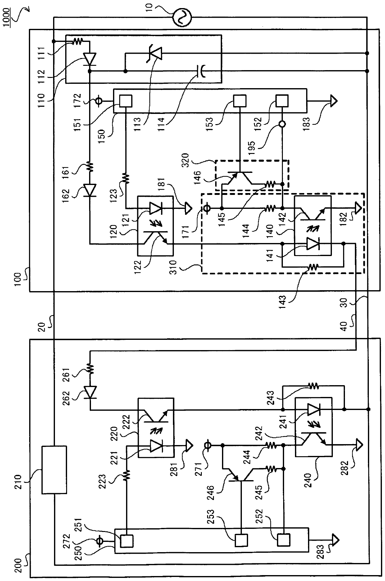
[0028] First, refer to figure 1 , and the configuration of the communication system 1000 according to Embodiment 1 of the present invention will be described. like figure 1 As shown, the communication system 1000 includes a communication device 100 and a communication device 200 . In this embodiment, the communication system 1000 is an air conditioning system, the communication device 100 is an outdoor unit, and the communication device 200 is an indoor unit. The communication device 100 is a transmitting device that transmits data to the communication device 200 and is also a receiving device that receives data from the communication device 200 . The communication device 200 is a transmitting device that transmits data to the communication device 100 and is also a receiving device that receives data from the communication device 100 . The communication device 100 and the communication device 200 are connected to each other by a 3-core cable including a power line 20 , a co...

Embodiment approach 2

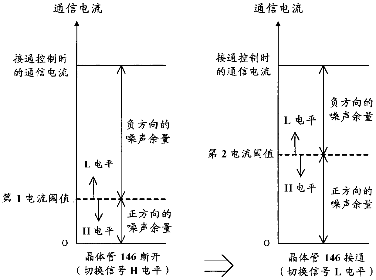
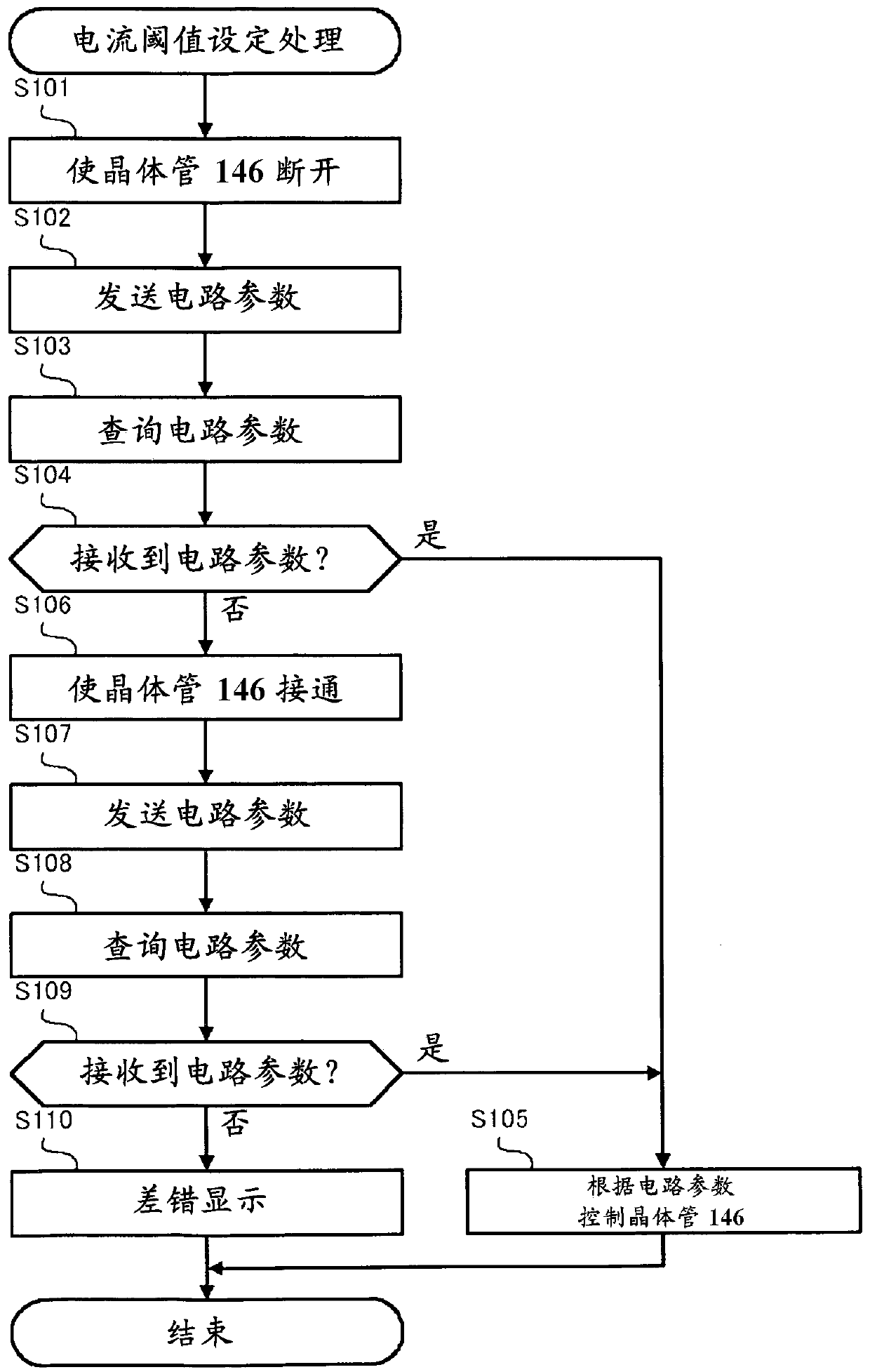
[0076] In Embodiment 1, an example in which the current threshold is switched in two steps of the first current threshold and the second current threshold has been described. In the present invention, the current threshold can also be switched in three or more steps. In this embodiment, an example in which the threshold current is switched in three stages of the first current threshold, the second current threshold, and the third current threshold will be described.

[0077] A communication system 1001 according to Embodiment 2 includes a communication device 101 and a communication device 201 . Communication device 101 includes transistor 147 between resistor 144 and power supply terminal 171 , and control unit 150 has the same configuration as communication device 100 except that it includes switching control unit 154 for switching the on state of transistor 147 . In addition, communication device 201 includes transistor 247 between resistor 244 and power supply terminal 27...

Embodiment approach 3

[0083] In Embodiment 1, the method of switching the current threshold value by switching the resistance value between the receiving terminal 195 and the power supply terminal 171 was described. In the present invention, the method of switching the current threshold is not limited to this method. In this embodiment, a method of switching the current threshold value by switching the resistance value between both ends of the light emitting diode 141 will be described.

[0084] like Image 6 As shown, a communication system 1002 according to Embodiment 3 includes a communication device 102 and a communication device 202 . Communication device 102 has the same configuration as communication device 100 except that resistor 131 and relay 132 are provided in series between both ends of light emitting diode 141 , and control unit 150 includes switching control unit 155 for controlling the state of relay 132 . The communication device 202 has the same configuration as the communicatio...


PUM


Abstract

A voltage application circuit (310) provided with a photocoupler (140) and a resistor (144) applies, to a reception terminal (195), a voltage corresponding to the magnitude of a communication currentflowing through a transmission path. A reception control unit (152) determines the presence or absence of the communication current by means of a comparison between the voltage applied to the reception terminal (195) and a predetermined voltage threshold. A voltage adjustment circuit (320) provided with a resistor (145) and a transistor (146) adjusts the voltage applied to the reception terminal (195) by the voltage application circuit (310). A switching control unit (153) switches a current threshold for determining the presence or absence of the communication current by controlling the voltage adjustment circuit (320) in accordance with the magnitude of the communication current at the time of ON control.

Description

technical field [0001] The present invention relates to a receiving device and a communication system. Background technique [0002] Currently, there is known an air conditioning system that connects a plurality of air conditioners to each other through a 3-core cable including a power supply line, a communication line, and a common line, and implements power supply and communication using the 3-core cable. In such an air-conditioning system, communication is realized using a current loop, which is a communication method for transmitting signals through changes in communication current. In this case, for example, a power supply circuit, a communication line, and a common line included in an outdoor unit among a plurality of air conditioners are connected in series to form a transmission path through which a communication current flows. Furthermore, each of the plurality of air conditioners includes a transmission circuit for controlling on / off (energization / off) of the comm...

Claims


Application Information

Patent Timeline
IPC IPC(8): H04L25/02F24F11/56
CPCH04L25/0278F24F11/89H04B1/10H04B1/16
Inventor 小竹弘晃石原正裕
Owner MITSUBISHI ELECTRIC CORP
Why Eureka
Try Eureka