Whole-bridge circuit of raising anti-noise function

A full-bridge circuit, anti-noise technology, applied in the direction of irreversible DC power input conversion to AC power output, etc., can solve the problems of poor anti-noise ability, less selectivity, complex circuit structure, etc., and achieve high anti-noise ability , The effect of simplifying the circuit design

Active Publication Date: 2005-12-21
DELTA ELECTRONICS INC
View PDF0 Cites 0 Cited by
  • Summary
  • Abstract
  • Description
  • Claims
  • Application Information

AI Technical Summary

Problems solved by technology

Also due to its low-voltage driving characteristics, the ability to resist noise in the circuit is relatively poor, and it is easy to cause malfunction due to the instantaneous floating voltage of the ground in the circuit
At the same time, such electronic components have less selectivity and cannot effectively reduce production costs
In addition, the switch Q in the full bridge circuit 12 1 , Q 2 , Q 3 , Q 4 It needs to be controlled by the control signals output by four microprocessor control units, so the circuit structure is relatively complicated

Method used


Image

  • Whole-bridge circuit of raising anti-noise function
  • Whole-bridge circuit of raising anti-noise function
  • Whole-bridge circuit of raising anti-noise function

Examples


Embodiment Construction

[0017] A full-bridge circuit with improved anti-noise function according to a preferred embodiment of the present invention will be described below with reference to related figures, wherein the same components will be described with the same reference symbols.

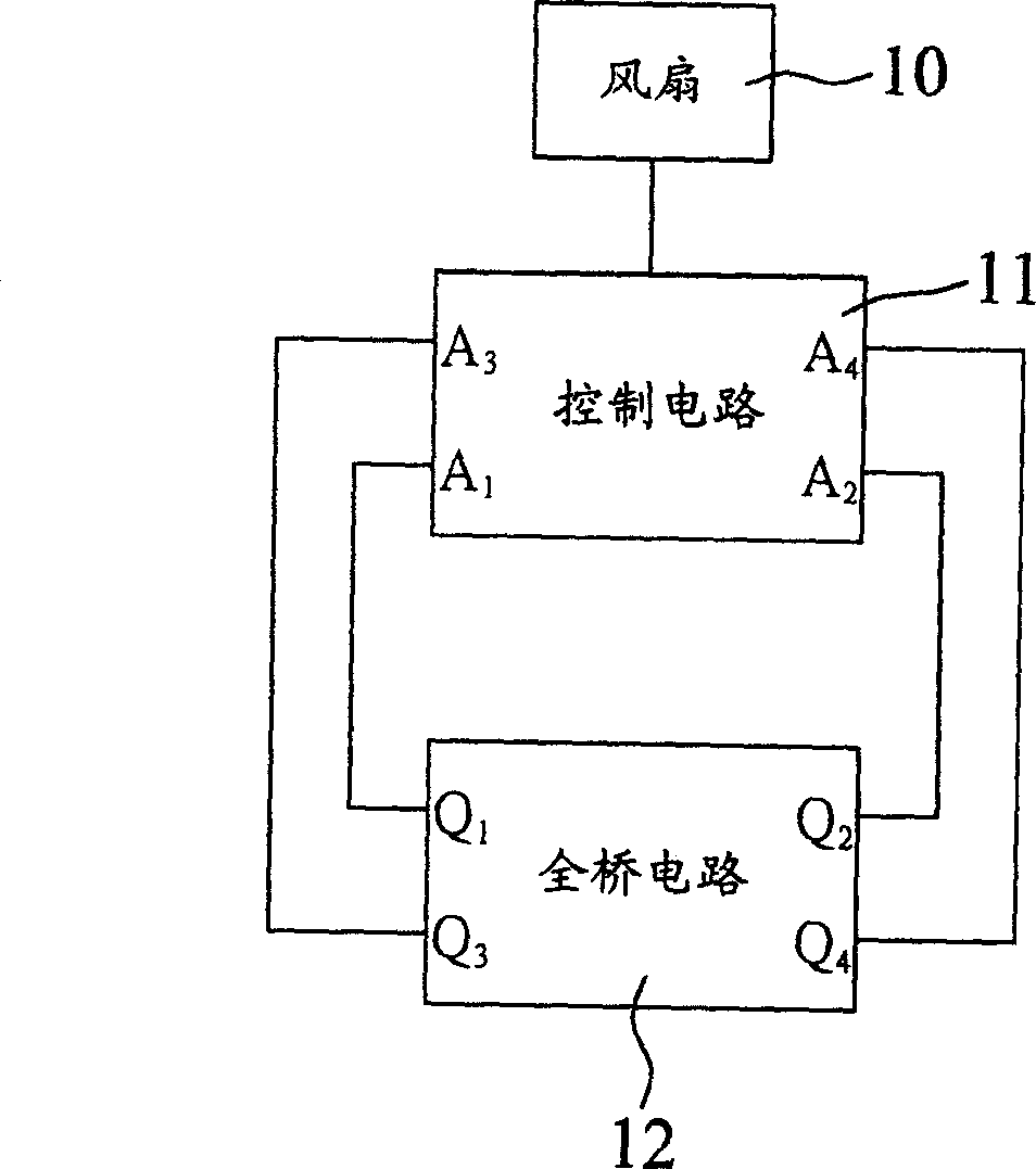
[0018] The full-bridge circuit for improving the anti-noise function of the present invention is applied in a heat dissipation system, and the heat dissipation system further includes a heat dissipation fan and a control circuit. The heat dissipation fan is used to blow a heat dissipation object (not shown) to achieve a heat dissipation effect. The control circuit is also similar to the conventional control circuit, that is, the output control signal is used to control the ON / OFF state of the switch in the full bridge circuit, for example, a microprocessor control unit is used to output the control signal. In other words, the overall structure of the cooling system of the present invention is as Figure 1a The structu...


PUM


Abstract

The full bridge circuit is applicable to a cooling system. The cooling system contains a heat elimination fan and a control circuit. The control circuit outputs a first control signal and a second control signal. The full bridge circuit includes a first branch line and a second branch line connected to each other in parallel, and an induction coil. The first branch line is composed of cascaded first switch and third switch, and the second branch line is composed of cascaded second switch and forth switch. One end of the induction coil is connected between first switch and third switch, and the other end of the induction coil is connected between second switch and forth switch. First control signal and second control signal drive first switch and second switch respectively, and turn them to ON/OFF. First control signal and second control signal also drive third switch and fourth switch respectively, and turn them to ON/OFF, but another drive power source is applied.

Description

【Technical field】 [0001] The invention relates to a full-bridge circuit, in particular to a full-bridge circuit applied to a cooling system and improving the anti-noise function. 【Background technique】 [0002] Please refer to Figure 1a and Figure 1b . Figure 1a It is a functional block diagram of a conventional cooling system. Figure 1b system display Figure 1a The circuit diagram of the driving method of the full bridge circuit in . Such as Figure 1a As shown, the conventional cooling system is mainly composed of a cooling fan 10 , a control circuit 11 and a full bridge circuit 12 . The driving mode of the full bridge circuit 12 is as follows: Figure 1b As shown, when the switch Q in the full bridge circuit 12 1 with switch Q 4 In the ON state, the switch Q 2 with switch Q 3 is OFF state so that the input voltage source V in The current flow path for the switch Q 1 , induction coil L and switch Q 4 . Conversely, when the switch Q in the full bridge circui...

Claims


Application Information

Patent Timeline
Patent Type & Authority Applications(China)
IPC IPC(8): H02M7/48
Inventor 邱进发邱俊隆曾伟硕蔡明熹
Owner DELTA ELECTRONICS INC
Why Eureka
Try Eureka