
Pruning device for road greening

A pruning device and road technology, applied in application, road surface cleaning, cutting tools, etc., can solve the problems of low pruning efficiency, increased labor costs, time-consuming and labor-intensive problems, and achieve good pruning effect, high pruning efficiency, and convenient use.

Pending Publication Date: 2019-11-08
ANHUI POLYTECHNIC UNIV
View PDF0 Cites 6 Cited by
  • Summary
  • Abstract
  • Description
  • Claims
  • Application Information

AI Technical Summary

Problems solved by technology

The shrub vegetation in the green belt needs to be pruned regularly. The green belt pruning work in the prior art is usually trimmed by a manual hand-held pruning machine. Because the pruning machine is relatively heavy, pruning is troublesome, time-consuming and laborious, and the neatness of pruning cannot be guaranteed.
In addition, there are also some pruning machine arms or pruning devices used for green belts. They are more complicated in structure, take up a lot of space, and cannot be stored. They generally can only prune the top or side of the shrub at the same time. It takes a certain amount of time to switch between the top pruning state and the side pruning state. Therefore, the overall pruning efficiency is relatively low whether the pruning machine is manually held, or the pruning machine arm or pruning device is used.
In addition, when the pruning machine, the pruning machine arm and the pruning device are used for pruning work, some of the pruned branches and leaves will fall on the road, and other cleaning personnel will be needed to clean them later, which increases labor costs and reduces the overall cost of pruning work. work efficiency

Method used


Image

  • Pruning device for road greening
  • Pruning device for road greening
  • Pruning device for road greening

Examples


Embodiment Construction

[0027] In order to make the technical means, creative features, goals and effects achieved by the present invention easy to understand, the present invention will be further described below in conjunction with specific embodiments.

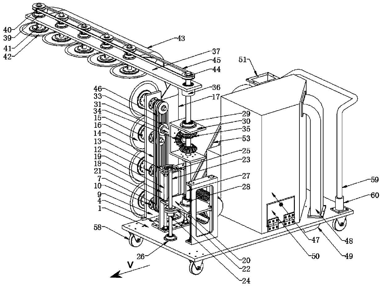
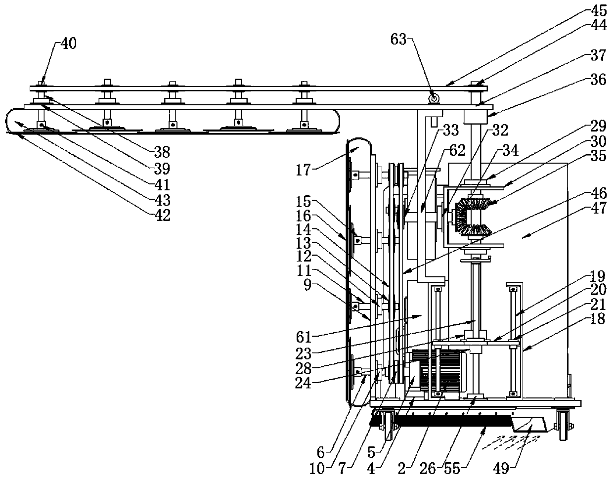
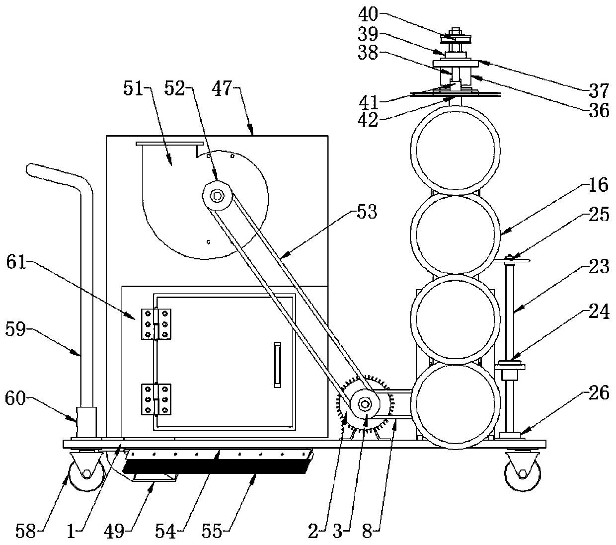
[0028] like Figure 1 to Figure 9 Shown, a kind of pruning device for road greening comprises a support plate 1 and a side pruning mechanism located on the support plate 1, an upper pruning mechanism and a branch and leaf cleaning mechanism, the support plate 1 is horizontal and is set towards the front and rear, The side pruning mechanism is arranged on the front left side of the support plate 1 and is used for trimming the side branches and leaves of the shrub. The branches and leaves cleaning mechanism is located in the middle of the back of the support plate 1 and is used to clean up the branches and leaves falling on the road surface when the shrubs are trimmed by the side pruning mechanism and the top pruning mechanism.

[0029] In the pres...


PUM


Abstract

The invention relates to the technical field of pruning equipment and discloses a pruning device for road greening. The pruning device comprises a supporting plate, a lateral pruning mechanism, an upper pruning mechanism and a branch and leaf clearing mechanism, the lateral pruning mechanism, the upper pruning mechanism and the branch and leaf clearing mechanism are arranged on the supporting plate, and the supporting plate is horizontal and arranged longitudinally. The lateral pruning mechanism is arranged on the front left side of the supporting plate and used for pruning lateral branches and leaves of shrubs; the upper pruning mechanism is arranged in the front middle of the supporting plate and used for pruning upper branches and leaves of the shrubs; the branch and leaf clearing mechanism is arranged in the rear middle of the supporting plate and used for clearing branches and leaves falling on a road surface in shrub pruning with the lateral pruning mechanism and the upper pruning mechanism. The lateral pruning mechanism comprises first blades and a driving motor; the upper pruning mechanism comprises a lifting plate, a screw rod and second blades; the branch and leaf clearing mechanism comprises a clearing tank, a conveying pipe and a collection pipe. The pruning device for road greening has advantages of reasonable structure, convenience in use, great pruning effects and high pruning efficiency.

Description

technical field [0001] The invention relates to the technical field of pruning equipment, in particular to a pruning device for road greening. Background technique [0002] Setting up green belts on both sides of the road can, on the one hand, beautify the urban environment, and on the other hand, reduce environmental pollution and absorb vehicle exhaust. The shrub vegetation in the green belt needs to be pruned regularly. The green belt pruning work in the prior art is usually trimmed by a manual hand-held pruning machine. Because the pruning machine is relatively heavy, pruning is troublesome, time-consuming and laborious, and the neatness of pruning cannot be guaranteed. . In addition, there are also some pruning machine arms or pruning devices used for green belts. They are more complicated in structure, take up a lot of space, and cannot be stored. They generally can only prune the top or side of the shrub at the same time. It takes a certain amount of time to switch ...

Claims


Application Information

Patent Timeline
Patent Type & Authority Applications(China)
IPC IPC(8): A01G3/08E01H1/08
CPCA01G3/08E01H1/0836
Inventor 时培成张征宇唐红晶夏仙阳刘光中
Owner ANHUI POLYTECHNIC UNIV
Learn More