
Automatic polishing device for broken end of wire rod bending machine

A bending machine and automatic technology, which is applied in the direction of grinding drive, grinding machine, grinding feed movement, etc., can solve the problems of no protection for the control panel of the bending machine, and the inability to break and grind the wire, and achieve a simple structure , to avoid the effect of being accidentally touched

Pending Publication Date: 2019-11-08
浙江剑麟金属制品有限公司
View PDF1 Cites 0 Cited by
  • Summary
  • Abstract
  • Description
  • Claims
  • Application Information

AI Technical Summary

Problems solved by technology

[0004] The purpose of the present invention is to solve the shortcomings in the prior art that the broken end of the wire cannot be polished, and the control panel of the bending machine has no protection, and proposes an automatic grinding device for the broken end of the wire bending machine

Method used


Image

  • Automatic polishing device for broken end of wire rod bending machine
  • Automatic polishing device for broken end of wire rod bending machine
  • Automatic polishing device for broken end of wire rod bending machine

Examples


Embodiment 1

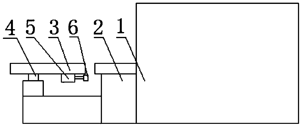
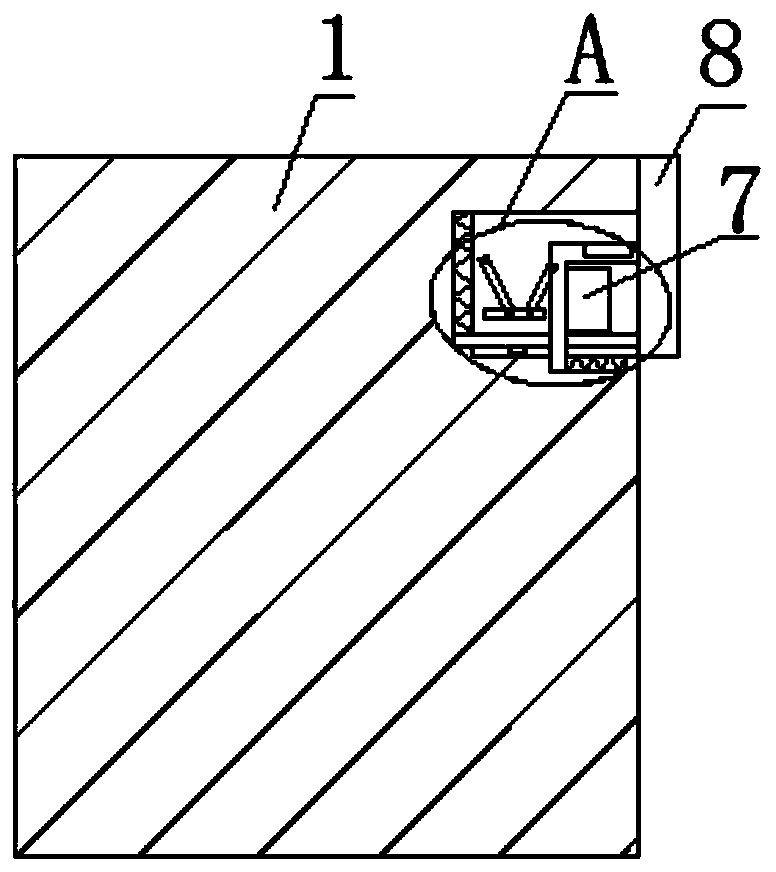
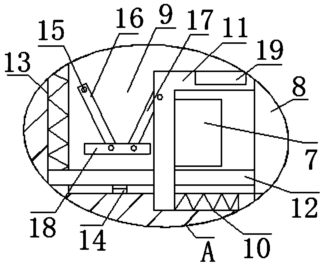
[0020] refer to Figure 1-3 , a wire bending machine broken end automatic grinding device, including a bending machine 1, one side of the bending machine 1 is provided with a discharge platform 2 and a blanking platform 3, the bending machine 1 is provided with a control panel 7, the bending machine A cylinder 4 is fixedly installed on the bending machine 1, and the output end of the cylinder 4 is fixedly installed on the bottom side of the unloading platform 3, and a motor 5 is fixedly installed on the bottom side of the unloading platform 3, and the output shaft of the motor 5 is fixedly installed through a coupling There is a rotating shaft, and one end of the rotating shaft is fixedly installed with a grinding head 6, and one side of the bending machine 1 is provided with a mounting groove 9, and a chute 10 is provided on the inner wall of the bottom side of the mounting groove 9, and an L-shaped The plate 11 and the control panel 7 are installed on one side of the L-shape...

Embodiment 2

[0026] refer to Figure 1-3 , a wire bending machine broken end automatic grinding device, including a bending machine 1, one side of the bending machine 1 is provided with a discharge platform 2 and a blanking platform 3, the bending machine 1 is provided with a control panel 7, the bending machine The bending machine 1 is fixed with a cylinder 4 by bolts, the output end of the cylinder 4 is fixed on the bottom side of the unloading platform 3 by bolts, the bottom side of the unloading platform 3 is fixed with a motor 5 by bolts, and the output shaft of the motor 5 A rotating shaft is fixedly installed by welding through a coupling, and one end of the rotating shaft is fixed with a grinding head 6 by a bolt. One side of the bending machine 1 is provided with a mounting groove 9, and a chute 10 is provided on the inner wall of the bottom side of the mounting groove 9. , an L-shaped plate 11 is slidably installed in the chute 10, and the control panel 7 is movably installed on ...


PUM


Abstract

The invention belongs to the field of wire rod bending machines, in particular to an automatic polishing device for a broken end of a wire rod bending machine. In order to solve the problem that the broken end of a wire rod cannot be polished and a control panel of the bending machine is not protected in the prior art, the invention provides a scheme as follows: the automatic polishing device comprises a bending machine. A discharging platform and an unloading platform are arranged on one side of the bending machine, a control panel is arranged on the bending machine, an air cylinder is fixedly mounted on the bending machine, an output end of the air cylinder is fixedly mounted on the bottom side of the unloading platform, a motor is fixedly mounted on the bottom side of the unloading platform, a rotating shaft is fixedly mounted on an output shaft of the motor through a coupling, a polishing head is fixedly mounted at one end of the rotating shaft, and a mounting groove is formed in one side of the bending machine. The automatic polishing device is simple in structure. The automatic polishing device polishes the wire rod by a polishing head, so that a manual polishing step is cancelled. Meanwhile, the control panel can be protected effectively, so that a risk of being collided mistakenly is avoided, and the demands of people are met.

Description

technical field [0001] The invention relates to the technical field of wire bending machines, in particular to an automatic grinding device for broken ends of wire bending machines. Background technique [0002] Wire rod is the smallest cross-sectional size of hot-rolled section steel. In my country, hot-rolled round steel with a diameter of 5-9 mm and a total of eight specifications is called wire rod. Because wire rod is delivered in coils, it is also called wire rod. Wire rod and wire bending is a commonly used production process in actual production. In factory production, wires are generally bent manually. This method is labor-intensive for workers, with low production efficiency and poor bending quality. The products have different shapes and are not suitable for modern industrial production. [0003] The patent with the publication number CN104308039B discloses a wire bending machine, which is driven by hydraulic control, has a compact structure, is convenient and quic...

Claims


Application Information

Patent Timeline
Patent Type & Authority Applications(China)
IPC IPC(8): B24B7/16B24B41/00B24B47/12
CPCB24B7/16B24B47/12B24B41/005
Inventor 王海王德刚
Owner 浙江剑麟金属制品有限公司
Learn More