Rubber material strip cutting machine with fast cutter changing function

A technology of slitting machine and function, applied in metal processing and other directions, can solve the problems of scattered, time-consuming and labor-intensive, affecting factory production efficiency, etc.

Pending Publication Date: 2019-11-08
安徽精致机电科技有限公司
View PDF1 Cites 3 Cited by
  • Summary
  • Abstract
  • Description
  • Claims
  • Application Information

AI Technical Summary

Problems solved by technology

The problem with the above-mentioned existing glue cutting mechanism is that the hobs of the traditional glue cutting machines are in the shape of a full circle, and the purpose is to cut out perfect straight strips of glue. However, since the cut glue strips are independent of each other , as soon as the rubber strips emerge from the exit of the glue cutting machine, they will be in a scattered state, which is not only not conducive to the collection of rubber strips, but also has an adverse effect on subsequent storage and transportation
The cutter shaft and the bearing seats on both sides of the traditional rubber cutting machine are all fixed in one structure. When changing the tool, the bearing seats on both sides must be disassembled as a whole, which is extremely time-consuming and laborious, and seriously affects the actual production efficiency of the factory.

Method used


Image

  • Rubber material strip cutting machine with fast cutter changing function
  • Rubber material strip cutting machine with fast cutter changing function
  • Rubber material strip cutting machine with fast cutter changing function

Examples


Embodiment Construction

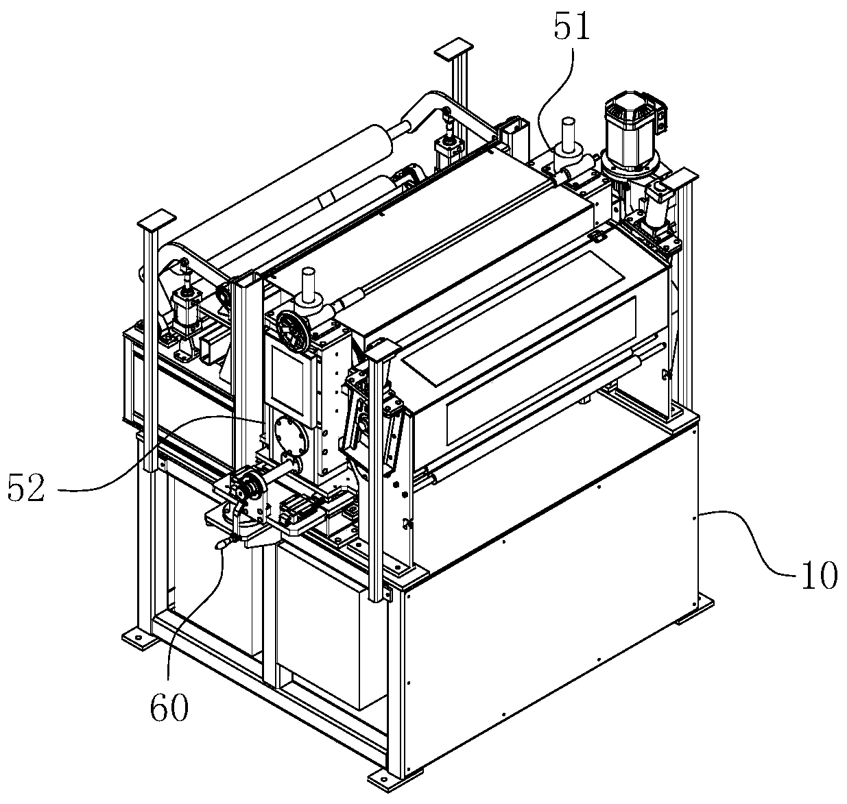
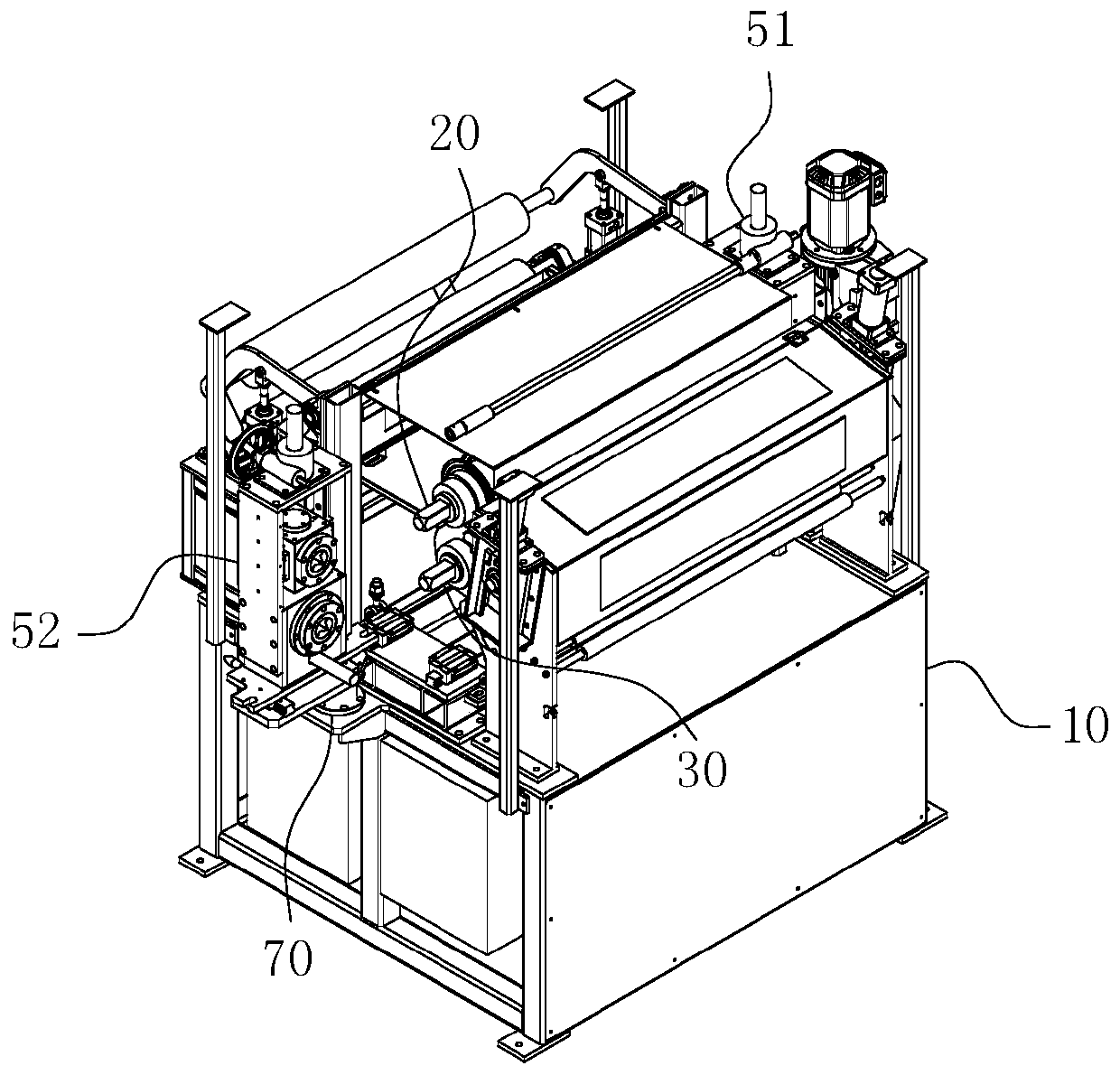
[0049] For ease of understanding, combined here Figure 1-13 , the concrete structure and working mode of the present invention are further described as follows:

[0050] The specific embodiment of the present invention is as Figure 1-2 As shown, its main structure includes a frame 10, on which a feed guide assembly, a cutter assembly and a discharge guide assembly are arranged, so that the rubber material can be guided by the rubber material guide assembly, and then cut and formed by the cutter assembly. Rubber strips, the rubber strips are exported through the discharge guide assembly, and finally delivered to the vulcanization area through packaging, storage and transportation processes. This improvement of the present invention is also aimed at the improvement of the cutter assembly. in:

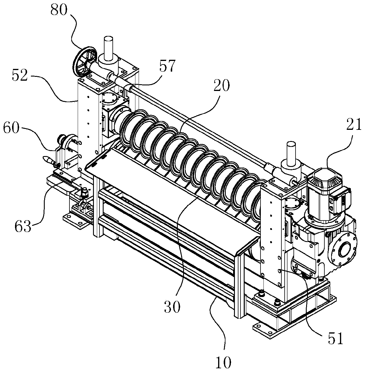
[0051] like Figure 3-12 As shown, the cutter assembly includes two sets of bearing supports, and an upper shaft body 20 and a lower shaft body 30 which are revolvingly fitted betwe...


PUM


Abstract

The invention belongs to the technical field of tire production and particularly relates to a rubber material strip cutting machine with a fast cutter changing function. The rubber material strip cutting machine with the fast cutter changing function comprises a rack and a cutter assembly; the cutter assembly comprises a fixed supporting base and a movable supporting base; the inner ring positionof a rotating bearing of the movable supporting base is coaxially sleeved with an inner shaft sleeve; and a hole and shaft inserting connection type bearing cooperation relationship is formed betweenthe corresponding shaft ends and/or the corresponding shaft end of an upper shaft body and/or a lower shaft body and the movable supporting base. The rubber material strip cutting machine further comprises a horizontal direction mold drawing mechanism which is fixedly connected to the rack through a rotating base, so that the horizontal direction mold drawing mechanism drives the movable supporting base till the inner shaft sleeve completely disengages from the shaft ends and/or the shaft end of the upper shaft body and/or the lower shaft body; the horizontal direction mold drawing mechanism can be used for driving the movable supporting base to generate a swinging action and completely avoid the axial direction disassembling and assembling path of hobbing cutters and/or a hobbing cutter at the position of the upper shaft body and/or the lower shaft body. The rubber material strip cutting machine with the fast cutter changing function can efficiently achieve the fast cutter changing requirement on the hobbing cutter, and has the advantages of further improving the production efficiency and making cutter changing operation easy, convenient and fast.

Description

technical field [0001] The invention belongs to the technical field of tire production, and in particular relates to a rubber strip cutting machine with the function of quick tool change. Background technique [0002] As we all know, injection vulcanization molding is a common rubber molding method in the field of rubber manufacturing. Injection vulcanization molding needs to pre-divide the rubber compound refined by the traditional internal mixer into long strips, and then inject the long strips of rubber into the molding mold by heating and extruding, which can significantly reduce the rubber product. Defects and air bubbles, improve the yield rate. However, in the current rubber production line, most of the cutting operations on rubber materials are done by manual cutting or guillotine. Obviously, the above-mentioned manual cutting method consumes a lot of labor, which not only increases the manufacturing cost, but also affects the production efficiency. At the same ti...

Claims


Application Information

Patent Timeline
Patent Type & Authority Applications(China)
IPC IPC(8): B26D1/22B26D7/26B26D3/00
CPCB26D1/22B26D3/003B26D7/2621B26D7/2635
Inventor 王运斌胡寅坤
Owner 安徽精致机电科技有限公司
Why Eureka
Try Eureka