Arrangement method of a distributed optical fiber sensor

A technology of distributed optical fibers and layout methods, applied in the directions of instruments, measuring devices, measuring instrument components, etc., can solve the problems of slow paving speed of asphalt surface, difficult leveling, and increased difficulty in grooving, so as to ensure smoothness and smoothness. Overall, the production process is simple, the effect of slowing down the rhythm of the layout

Active Publication Date: 2021-03-09
HARBIN INST OF TECH
View PDF9 Cites 0 Cited by
  • Summary
  • Abstract
  • Description
  • Claims
  • Application Information

AI Technical Summary

Problems solved by technology

First, the speed of asphalt surface paving is slow, and the increase in cross-section distance increases the waiting time before laying; secondly, the number of slots required for optical fiber laying is large and the size is long, and the cooling and hardening of local mixture is accelerated during the slotting process. increase; again, applying micro-prestress to long-distance optical fibers takes a long time to install; finally, long distances lead to increased time consumption for slotting and backfilling
In summary, the increase in the time consumption of each link leads to a longer deployment cycle
[0008] 2. Slotting is difficult
In the process of long-distance grooving, the surface layer cools and hardens with time, and the use of tools such as electric picks and iron picks increases the difficulty of grooving, and it is difficult to ensure the flatness of the groove
[0010] 3. The sensor fixation effect is not good
[0011] At present, clamping blocks or pressure heads and screws or screws are commonly used to fix the sensor, but in the process of paving the road, the sensor is prone to slipping and splitting under the action of the mixture; in order to improve the fixing effect, usually Use normal temperature glue to bond the sensor and clamping block or indenter. Although the fixing effect can be achieved, the curing time of the normal temperature glue is slow, which is inconvenient for on-site construction
[0012] 4. The effect of backfilling is difficult to guarantee
However, in actual operation, the width of the slot is similar to the diameter of the optical fiber. After installing the distributed optical fiber, it is difficult for the backfill to enter the bottom of the groove and leveling is difficult. bad

Method used


Image

  • Arrangement method of a distributed optical fiber sensor
  • Arrangement method of a distributed optical fiber sensor
  • Arrangement method of a distributed optical fiber sensor

Examples


specific Embodiment approach 1

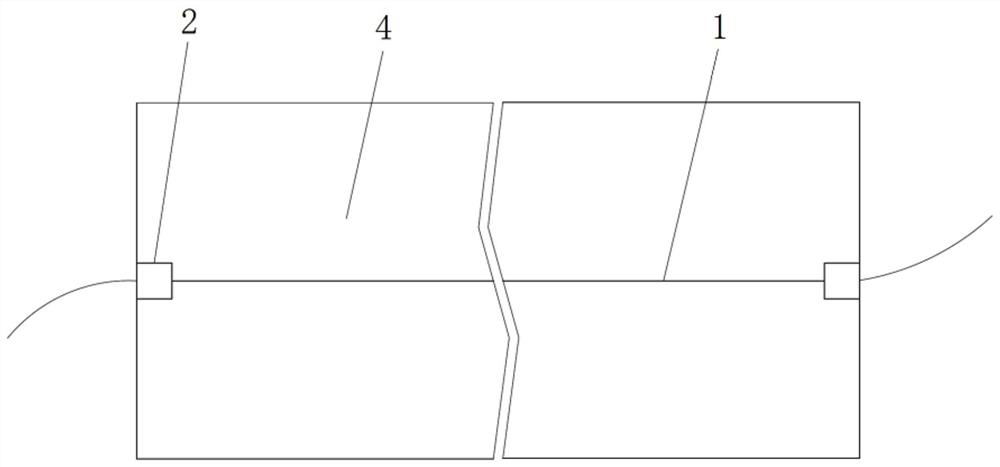
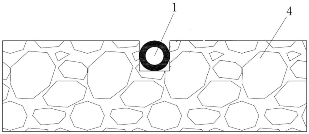
[0033] Specific implementation mode one: combine Figure 1-Figure 2 To illustrate this embodiment, a method for arranging distributed optical fiber sensors on asphalt roads in this embodiment includes the following steps:

[0034] A. Install fixed seats 2 that restrict axial movement at both ends of the existing distributed optical fiber sensor 1, and coat the surface of the distributed optical fiber sensor 1 with a thermoplastic colloid material;

[0035] B. Slotting the existing pavement 4, expanding the position where the notch on the pavement 4 is installed with the fixing seat 2 to ensure that the fixing seat 2 is smoothly installed into the groove of the road surface 4;

[0036] C. Fix the fixed seat 2 in the groove of the road surface 4, fill the mixed high-temperature asphalt mixture into the groove of the road surface 4 when the road surface 4 is paved, and the thermoplastic colloid coated on the surface of the distributed optical fiber sensor 1 will be caused by the ...

specific Embodiment approach 2

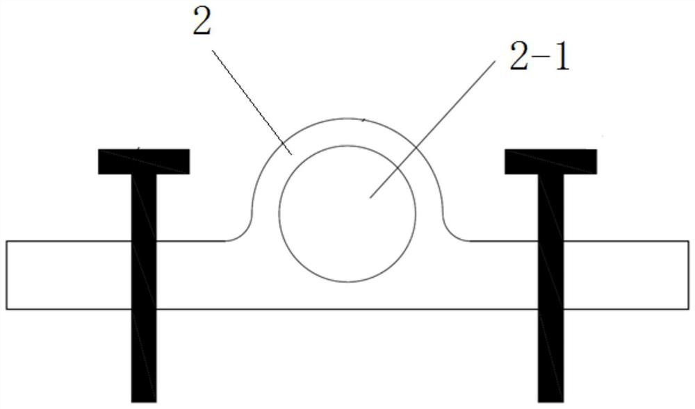
[0037] Specific implementation mode two: combination image 3 and Figure 4 To illustrate this embodiment, in step A of this embodiment, before installing the fixing seat 2, the two ends of the distributed optical fiber sensor 1 are respectively processed with annular grooves, and then two sets of semi-circular rings 3 are processed, each set of semi-circular rings 3 It consists of two symmetrical semi-circular rings 3, the inner surface of each semi-circular ring 3 is processed with a protrusion matching the annular groove, and the outer surface of each semi-circular ring 3 is processed with threads. The circular ring 3 is fastened on both ends of the distributed optical fiber sensor 1, and the fixed seat 2 is processed with a threaded hole 2-1, and each set of semi-circular rings 3 is screwed into the threaded hole 2-1 of the fixed seat 2 Inside.

[0038] In this embodiment, two semi-circular rings 3 are provided, and protrusions matching the annular grooves are arranged i...

specific Embodiment approach 3

[0040] Specific embodiment three: Step B of this embodiment uses GPS or a total station for positioning, and uses a cutting machine to cut the road surface 4, so that the grooves opened on the road surface 4 are straight and consistent in depth.

[0041] Such setting makes the slotting more accurate.

[0042] Its composition and connections are the same as those in the first embodiment.


PUM

PropertyMeasurementUnit
thicknessaaaaaaaaaa

Abstract

A method for distributing distributed optical fiber sensors, which belongs to the technical field of road detection, to solve the problems of long construction period, difficult slotting, poor fixing effect of sensors and difficulty in guaranteeing backfilling effect existing in laying sensors on asphalt pavement . The present invention comprises the following steps: A, respectively installing fixed seats restricting axial movement at both ends of the existing distributed optical fiber sensor, and coating the surface of the distributed optical fiber sensor with thermoplastic colloid material; B, applying the existing road surface Carry out slotting and expand the notches at both ends of the slotted road surface to ensure that the fixing seat is smoothly installed into the groove of the road surface; The mixture is filled into the groove of the road surface, and the thermoplastic colloid material coated on the surface of the distributed optical fiber sensor is melted due to high temperature, so as to fill the gap around the distributed optical fiber sensor. The invention is applicable to the detection of asphalt pavement.

Description

technical field [0001] The invention relates to a method for arranging sensors on asphalt pavement, in particular to a method for arranging distributed optical fiber sensors, and belongs to the technical field of road detection. Background technique [0002] The intelligent sensing components used in asphalt pavement research are mainly point sensors and distributed optical fiber sensors. Distributed optical fiber sensors have gradually become a research hotspot in the industry because they can realize long-distance, full-section structural information monitoring and low cost. [0003] In terms of road soil foundation and slope monitoring, the optical fiber sensor is generally pasted on the surface of the measuring tube, embedded in the slot, and the deformation of the soil body is obtained by using the strain of the measuring tube. Different from sensors embedded in the soil, the deployment process of optical fiber sensors on asphalt pavement is more complicated. It is req...

Claims


Application Information

Patent Timeline
Patent Type & Authority Patents(China)
IPC IPC(8): E01C23/01G01D11/30
CPCE01C23/01G01D11/30
Inventor 董泽蛟李环宇隋鑫马宪永全蔚闻
Owner HARBIN INST OF TECH
Why Eureka
Try Eureka