A staggered high-efficiency enhanced geothermal injection-production single well structure and its completion method

An enhanced and staggered technology, applied in geothermal energy power generation, boreholes/well components, heat collectors using groundwater as the working fluid, etc., can solve the problem of poor heat transfer at the well end, difficulty in descaling, and impact on production Effect and other issues, to achieve the effect of easy descaling in the later stage, good practical application significance, and good economic benefits

Active Publication Date: 2022-03-08
祝学忠
View PDF4 Cites 0 Cited by
  • Summary
  • Abstract
  • Description
  • Claims
  • Application Information

AI Technical Summary

Problems solved by technology

[0002] The traditional single well recharge enhanced geothermal system uses the outer pipe to inject cold water into the well and the inner pipe to recharge hot water to the outside. The disadvantages of this method of producing water in the well pipe and injecting water from the inner pipe are: When the cold water reaches the end of the underground well pipe, because the front part of it has undergone preliminary heat exchange with the rock formation, the above-mentioned funnel of temperature drop near the wellhead will be formed. The temperature difference of the rock formation is small, and in the case of cluster wells, the production effect is affected, so this structure makes the heat transfer effect at the well end poor
In this case, descaling is very difficult, and the oil pipe needs to be removed for ground descaling

Method used


Image

  • A staggered high-efficiency enhanced geothermal injection-production single well structure and its completion method
  • A staggered high-efficiency enhanced geothermal injection-production single well structure and its completion method
  • A staggered high-efficiency enhanced geothermal injection-production single well structure and its completion method

Examples


Embodiment Construction

[0028] Embodiments of the technical solutions of the present invention will be described in detail below in conjunction with the accompanying drawings. The following examples are only used to illustrate the technical solutions of the present invention more clearly, and therefore are only examples, rather than limiting the protection scope of the present invention.

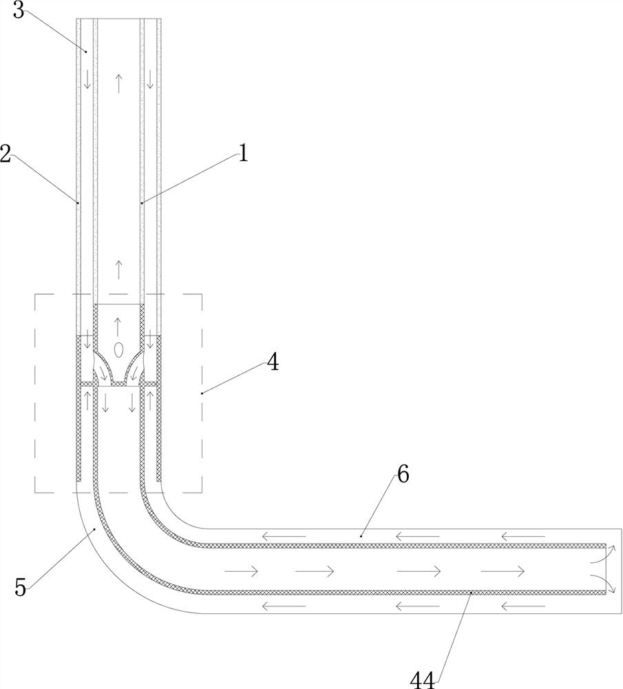
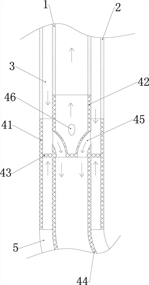
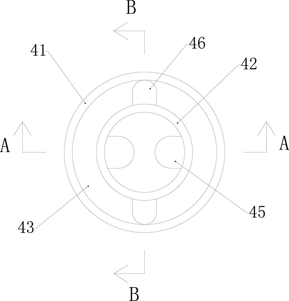
[0029] Such as Figure 1-6 As shown in , a staggered high-efficiency enhanced geothermal injection-production single well structure includes an inner pipe 1 and an outer pipe 2 arranged in a vertical well section, the inner pipe 1 and the outer pipe 2 are arranged coaxially, and the inner pipe 1 An annular space 3 is formed between the pipe 1 and the outer pipe 2, and a conversion mechanism 4 is installed in the vertical well section below the inner pipe 1 and the outer pipe 2, and the conversion mechanism 4 is used to direct cold water from it to the center of the well bottom The end flows out, and is used to con...


PUM


Abstract

The invention relates to the field of enhanced geothermal well completion construction methods, in particular to a staggered high-efficiency enhanced geothermal injection-production single well structure and a well completion method thereof, including an inner pipe and an outer pipe arranged in a vertical well section, the inner pipe and the outer pipe The outer pipe is coaxially arranged, an annular space is formed between the inner pipe and the outer pipe, and a conversion mechanism is installed in the vertical well section below the inner pipe and the outer pipe, and the conversion mechanism is used to transfer cold water from it to It flows out to the central end of the bottom of the well, and is used to convert the hot water after heat exchange to the inner pipe for extraction. The overall structure design is convenient and reasonable, using the extension pipeline of the annular water injection center to inject water, so that the cold water flows out from the center, keeping the water temperature low to increase the temperature difference, improve the heat exchange effect, and high production efficiency; at the same time, considering the follow-up descaling problem , the use of conversion joints allows the hot water after heat exchange to be collected from the inner pipe, which realizes the water collection of the inner pipe and facilitates descaling in the later stage. It has good practical application significance and good economic benefits in actual use.

Description

technical field [0001] The invention relates to the field of enhanced geothermal well completion construction methods, in particular to a staggered high-efficiency enhanced geothermal injection-production single well structure and a well completion method. Background technique [0002] The traditional single well recharge enhanced geothermal system uses the outer pipe to inject cold water into the well and the inner pipe to recharge hot water to the outside. The disadvantages of this method of producing water in the well pipe and injecting water from the inner pipe are: When the cold water reaches the end of the underground well pipe, because the front part of it has undergone preliminary heat exchange with the rock formation, the above-mentioned funnel of temperature drop near the wellhead will be formed. The temperature difference of the rock formation is small, and in the case of cluster wells, the production effect is affected, so this structure makes the heat exchange e...

Claims


Application Information

Patent Timeline
Patent Type & Authority Patents(China)
IPC IPC(8): E21B43/00E21B43/30E21B17/00E21B17/04F24T10/20
CPCE21B43/00E21B43/305E21B17/00E21B17/04F24T10/20Y02E10/10
Inventor 祝学忠
Owner 祝学忠
Why Eureka
Try Eureka