
ceiling fan

A ceiling fan and fan blade technology, applied in the field of ceiling fans, can solve the problems of loose parts, reduce the stability of ceiling fans, etc., and achieve the effects of not easy to loosen, firm loosening, and improved safety.

Active Publication Date: 2020-12-11
深圳市百达建筑室内设计有限公司
View PDF1 Cites 0 Cited by
  • Summary
  • Abstract
  • Description
  • Claims
  • Application Information

AI Technical Summary

Problems solved by technology

[0004] The above-mentioned existing technical solutions have the following defects: because the fan blades are fixedly arranged on the rotating seat, when the fan blades are disturbed by abnormal air flow and vibrate in the up and down direction, the vibration is easily transmitted from the fan blades to other parts of the ceiling fan. It makes other components on the ceiling fan also be affected by the fan blades to vibrate, which reduces the stability of the connection of the ceiling fan components, and is prone to loose parts, so it needs to be improved

Method used


Image

  • ceiling fan
  • ceiling fan
  • ceiling fan

Examples


Embodiment Construction

[0036] The present invention will be described in further detail below in conjunction with the accompanying drawings.

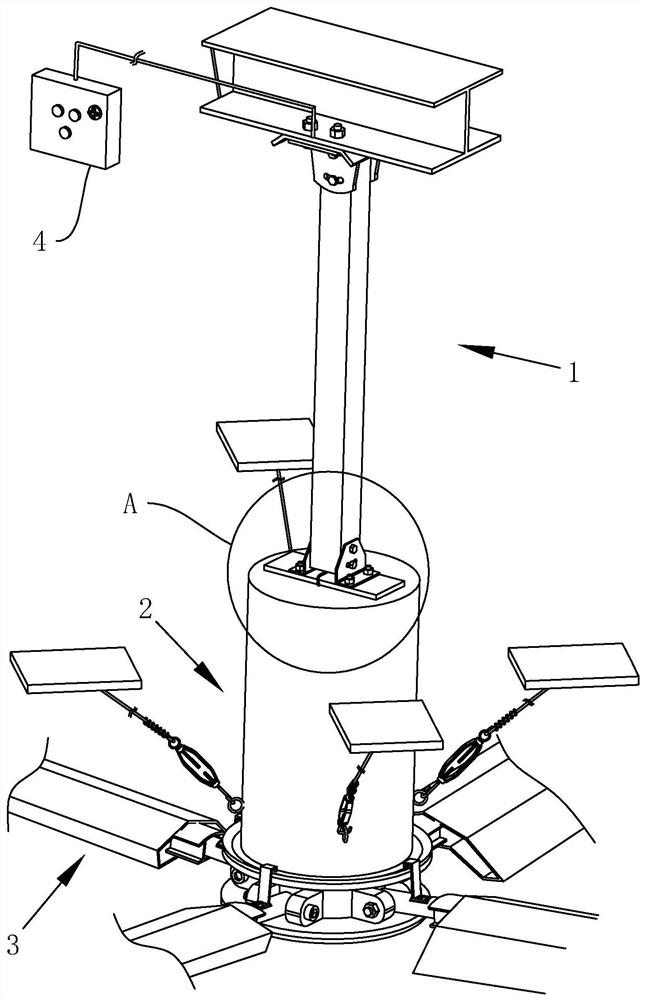
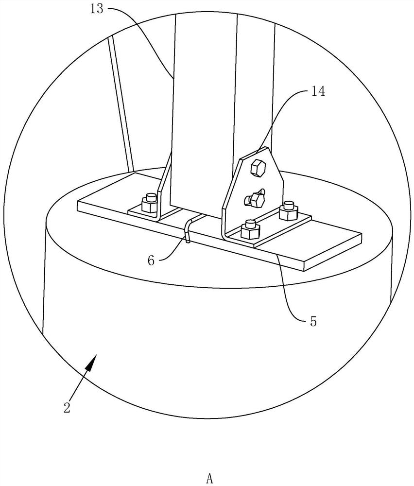
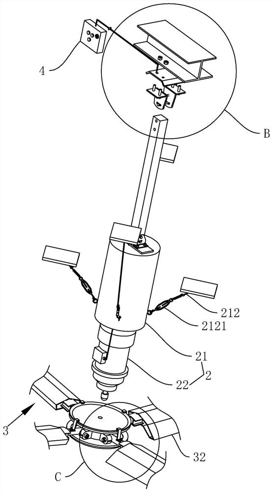
[0037] refer to figure 1 , is a ceiling fan disclosed in the present invention, comprising: an installation part 1, a drive part 2 and a fan blade 3, the installation part 1 is fixedly arranged above the drive part 2, the fan blade 3 is arranged below the drive part 2, and the fan blade 3 surrounds There are several pieces evenly distributed in the circumferential direction of the driving part 2, which can be three pieces, four pieces or five pieces, here are four fan blades 3, and the four fan blades 3 are evenly distributed around the periphery of the driving part 2 in the circumferential direction. Next to it is also provided with a control switch 4 that controls the opening and closing of the ceiling fan, the control switch 4 is connected with the ceiling fan by a wire, and the control switch 4 is a button switch.

[0038] refer to figure 2 and Figur...


PUM


Abstract

The invention relates to a ceiling fan, which includes: a hub, a driving part, a fan blade and a supporting plate. The hub is fixedly arranged at the lower end of the driving part and driven to rotate by the driving part. The fan blade is arranged adjacent to the hub and one end of the fan blade is connected to the hub shaft. The side surface is hinged, and the fan blade rotates up and down around the hinge. The supporting plate is fixedly installed on the lower end of the hub, and the upper surface of the supporting plate forms a barrier with the lower surface of the end of the fan blade close to the hub. The invention has the effect of reducing the transmission of vibration on the fan blades and improving the connection stability of each component on the ceiling fan.

Description

technical field [0001] The invention relates to the technical field of fans, in particular to a ceiling fan. Background technique [0002] Ceiling fan is a kind of fan. It is generally installed on the ceiling. Because of its long blades and a large range of agitating air, ceiling fans are generally installed in places with a large space range for the purpose of cooling down a wide range. [0003] In the prior art, there is a Chinese patent whose authorized announcement number is CN109268292A. In this patent, a rotating seat is fixedly arranged under the reducer, and the rotating seat is driven to rotate by the reducer. When rotating, the fan blades rotate together with the rotating seat, agitating the air and forming an air flow. [0004] The above-mentioned existing technical solutions have the following defects: because the fan blades are fixedly arranged on the rotating seat, when the fan blades are disturbed by abnormal air flow and vibrate in the up and down direction...

Claims


Application Information

Patent Timeline
Patent Type & Authority Patents(China)
IPC IPC(8): F04D25/08F04D29/64F04D29/36F04D29/66
CPCF04D25/088F04D29/646F04D29/36F04D29/666F04D29/601
Inventor 陈振东林登峰徐伽贺
Owner 深圳市百达建筑室内设计有限公司
Learn More