Eyeball tracking structure

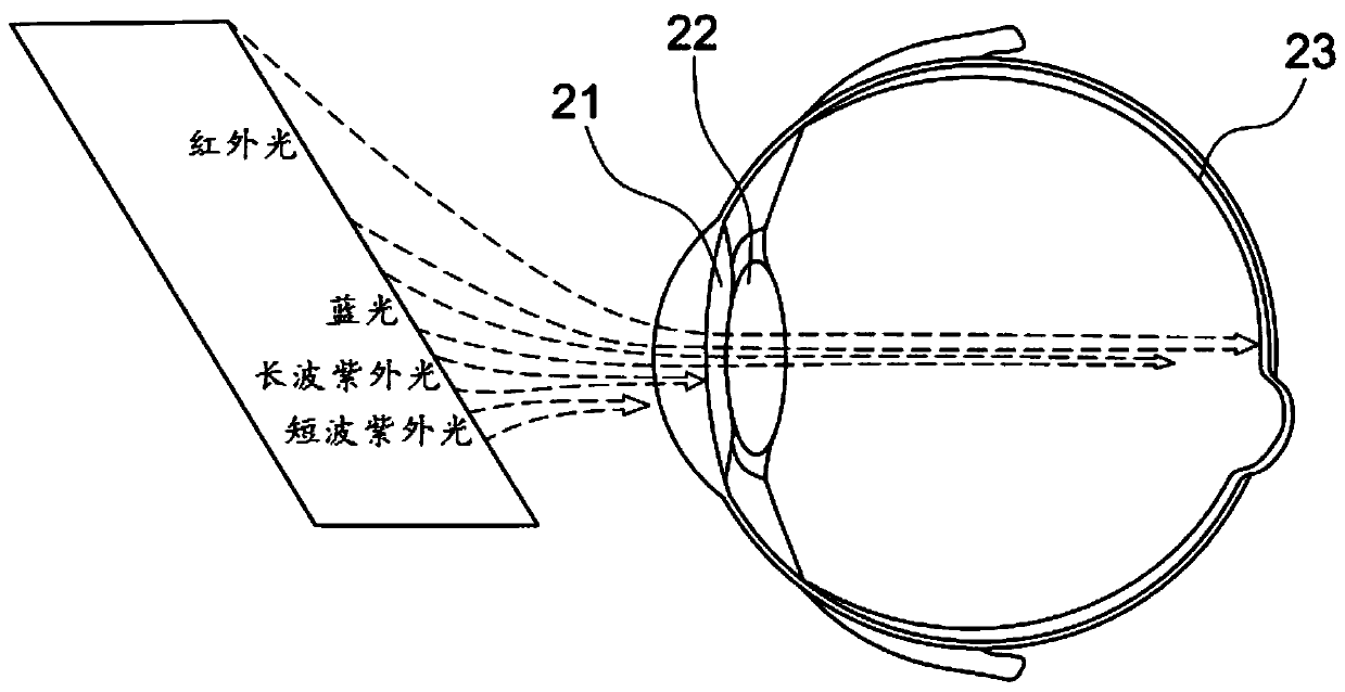
An eye tracking and eye technology, applied in TV, optics, instruments, etc., can solve problems such as retinal 23 burns

Active Publication Date: 2019-11-08
INTERFACE TECH CHENGDU CO LTD +2
View PDF11 Cites 5 Cited by
  • Summary
  • Abstract
  • Description
  • Claims
  • Application Information

AI Technical Summary

Problems solved by technology

[0005] At present, the technology of actively projecting infrared beams to extract features has better accuracy, please refer to figure 2 As shown, but considering that the infrared light beam will be absorbed by the iris 21 and lens 22 in the eye, it is easy to burn the retina 23, and it is more likely to cause cataract in the long run. How to stop the operation through safety monitoring in case of abnormality has always been the focus of technology development
[0006] It can be seen that there are still many deficiencies in the above-mentioned customary items, which are not a good designer and need to be improved urgently.

Method used


Image

  • Eyeball tracking structure
  • Eyeball tracking structure
  • Eyeball tracking structure

Examples


Embodiment Construction

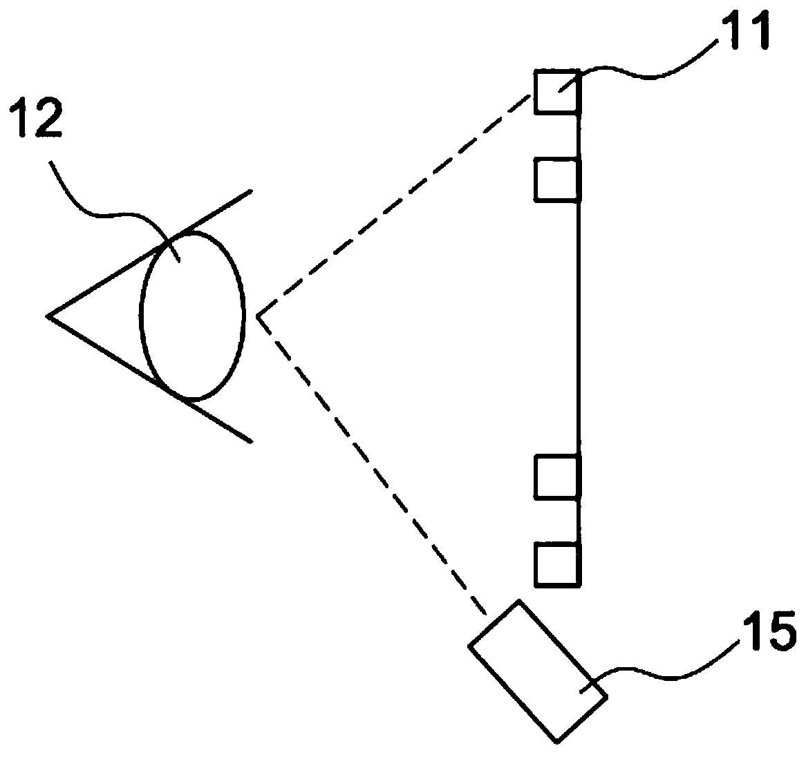
[0033] The present invention is related to an "eye tracking framework", please refer to image 3 , Figure 4 , Figure 5 As shown, the eye tracking framework of the present invention mainly includes: a hot mirror (Hot Mirror) 30 , an infrared light source 40 and a camera 50 .

[0034] Wherein, the hot mirror 30 is arranged between a display 31 and a human eye 32 in a head-mounted display device for reflecting infrared rays.

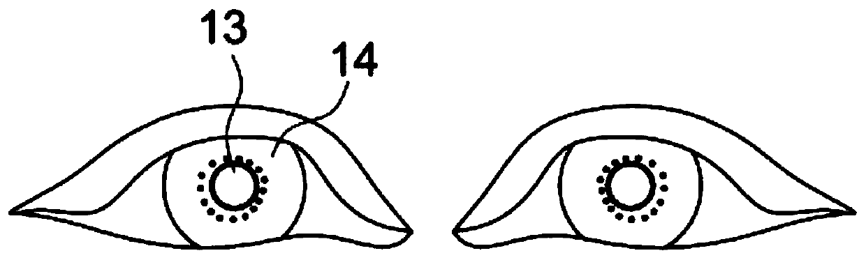
[0035] The infrared light source 40 is located on one side of the display 31 in the head-mounted display device, and is electrically connected with the control circuit (not shown in the figure) of the head-mounted display device. The control circuit can control the infrared light source 40 to project The infrared light spot 41 for measuring the moving track of the eye is placed on the hot mirror 30 , so that the hot mirror 30 reflects the infrared light spot 41 to form an infrared pattern (IR Pattern) 42 .

[0036] The camera 50 is located on the other...


PUM


Abstract

An eyeball tracking structure comprises a heat mirror, an infrared light source and a camera. The heat mirror is arranged between a displayer in a head-mounted display device and a human eye; the camera is arranged on one side of the displayer in the head-mounted display device, connected with a control circuit and used for capturing an image of an infrared pattern reflected by the heat mirror, capturing an eye image of the human eye and transmitting an obtained composite image to the control circuit, so that the control circuit conducts compensation calculation through a sight image function,the position of a sight point on the displayer is calculated, and then the displayer is controlled to feed back and display information corresponding to the position. Therefore, speckles of infraredbeams are projected onto the heat mirror instead of being directly projected into the eyeball, and the situation that the infrared rays are directly projected onto the eyeball and cause harm can be avoided.

Description

technical field [0001] The present invention is an eye tracking architecture design, especially a design that adds a hot mirror (Hot Mirror) to the architecture, so that the speckle of the infrared beam is projected onto the hot mirror instead of directly projecting into the eyeball. Then use a camera (Camera) to compare the pupil and the infrared pattern (IR Pattern) on the thermal mirror to perform eye position and tracking calculations. Background technique [0002] By the way, eye tracking technology mainly started from medical research and development. After technology accumulation, it has entered the stage of commercial application and has been applied to different devices such as mobile phones, computers, and automobiles. With the development of the AR / VR industry, the foveated rendering technology derived from eye tracking can reduce the CPU computing load by 30%-70%. In addition to reducing hardware costs, it also helps to improve user experience. [0003] At pres...

Claims


Application Information

Patent Timeline
Patent Type & Authority Applications(China)
IPC IPC(8): G02B27/00G02B27/01G02B27/48
CPCG02B27/0093G02B27/0101G02B27/48G06F3/013H04N5/33G02B27/0172G02B2027/0187H04N23/11
Inventor 林柏青
Owner INTERFACE TECH CHENGDU CO LTD
Why Eureka
Try Eureka