Cable device facilitating video monitoring line wiring and using method thereof

A video monitoring and cable device technology, applied in the direction of cables, circuits, insulated cables, etc., can solve the problems of complicated construction procedures, inconvenience, and many construction contents, so as to improve the installation and fixing effect, enhance the bonding effect, and change the fixing way effect

Active Publication Date: 2019-11-08
ZHEJIANG ZHISHENG TECH
View PDF6 Cites 2 Cited by
  • Summary
  • Abstract
  • Description
  • Claims
  • Application Information

AI Technical Summary

Problems solved by technology

[0003] There are generally two ways for the existing weak current line wiring. One is to dig a wiring trough inside the wall. Wiring through the wiring trough, although this method will not leave traces on the outside of the wall after installation, and the lines will not be easily affected by the outside world after installation, but the installation process is more complicated, the wall needs to be destroyed, and the weak current lines When replacing or overhauling, a lot of construction content is required, which is not convenient for the staff. One is to fix the network cable on the outside of the wall through an external fixing device. This method causes less damage to the wall, but because the fixing device is relatively Many, there are certain requirements for the fixed wall, and the fixing effect is not high. At the same time, if the line needs to be repaired or replaced, all the original fixing devices need to be removed. The construction process is also complicated, which is not conducive to users adjust as needed

Method used


Image

  • Cable device facilitating video monitoring line wiring and using method thereof
  • Cable device facilitating video monitoring line wiring and using method thereof
  • Cable device facilitating video monitoring line wiring and using method thereof

Examples


Embodiment 1

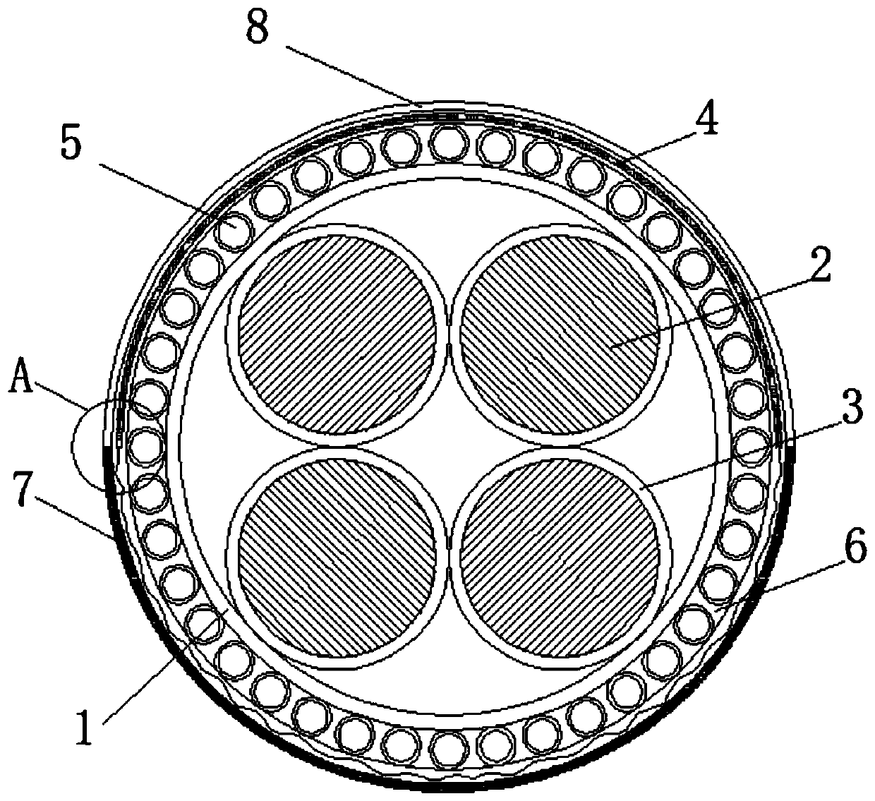
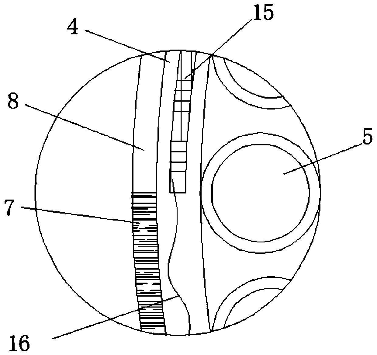
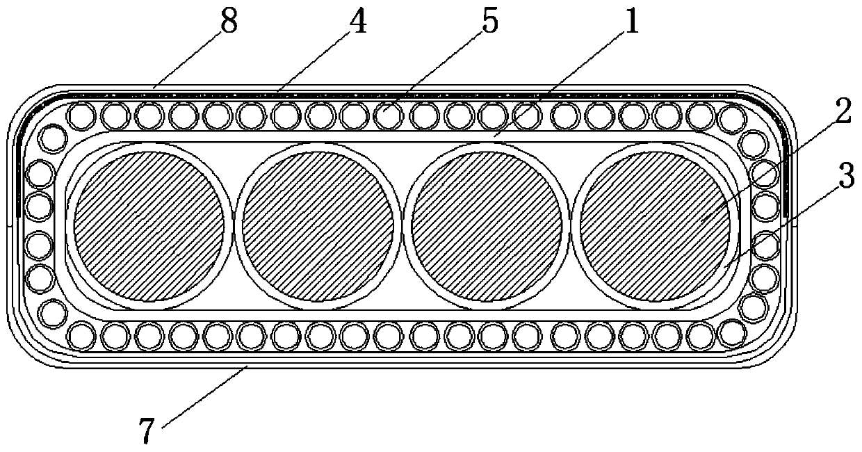
[0042] see Figure 1-5 , a cable device for convenient wiring of video surveillance lines and a method of use thereof, comprising an outer heat conduction layer 1, four branch video surveillance lines 2 are arranged inside the outer heat conduction layer 1, and outer end sleeves of the branch video surveillance lines 2 There is an insulating and heat-insulating layer 3, and the insulating and heat-insulating layer 3 is bonded to the inner wall of the outer heat-conducting layer 1. The layer is covered with a self-thermally deformable layer 4, and the outer layer of the self-thermally deformable layer 4 is covered with an external fixed cilia layer 7, the inner side of the externally fixed cilia layer 7 is fixedly connected with the outer end of the self-thermally deformable layer 4, and the self-thermally deformable layer 4 is connected to the outer heat-conducting layer. A plurality of polymerized and shaped skeleton tubes 5 are arranged between the layers 1, and the polymeri...


PUM


Abstract

The invention discloses a cable device facilitating video monitoring line wiring and a using method thereof and belongs to the field of weak current wiring. The cable device facilitating video monitoring line wiring comprises an outer heat conduction layer. The outer heat conduction layer is internally provided with four branch video monitoring lines. Each branch video monitoring line is externally sleeved by an insulated thermal insulation layer. The insulated thermal insulation layers are attached to the inner wall of the outer heat conduction layer. The branch video monitoring lines are insliding connection to the inner wall of the outer heat conduction layer through the insulated thermal insulation layers. The outer heat conduction layer is externally sleeved by a self-heating deformation layer. When the video monitoring cables are installed, the internal side-by-side lines can deform according to the shape of the wall, and can be arbitrarily shaped after being deformed, thereby enhancing the attaching effect to the wall surface; and by changing the fixation mode, damage to the wall by video monitoring line wiring during installation of the video monitoring lines is reduced, and the wiring mode and fixation position can be adjusted at will according to the needs of users.

Description

technical field [0001] The invention relates to the field of weak current wiring engineering, and more specifically, relates to a cable device for facilitating wiring of video surveillance lines and a method for using the same. Background technique [0002] Video surveillance lines are part of weak current lines. In the process of implementing weak current intelligentization, weak current lines are mainly aimed at buildings, including buildings, communities, airports, docks, railways, expressways, etc. Common working voltages of weak current systems include: 24VAC, 16.5VAC, 12VDC, and sometimes 220VAC is also considered a weak current system. Intelligent systems are classified into six categories according to the national design code "Building Intelligent Design Standards" (GB50314-2015). System: intelligent integrated system, information facility system, information application system, construction equipment management system, public safety system, computer room engineering...

Claims


Application Information

Patent Timeline
Patent Type & Authority Applications(China)
IPC IPC(8): H01B7/00H01B7/02H01B7/40H01B7/42
CPCH01B7/0045H01B7/02H01B7/40H01B7/428
Inventor 李杰
Owner ZHEJIANG ZHISHENG TECH
Why Eureka
Try Eureka