Eureka AIR delivers breakthrough ideas for toughest innovation challenges, trusted by R&D personnel around the world.

Photovoltaic module based on diffractive optical element and manufacturing method thereof

A diffractive optical element and photovoltaic module technology, applied in photovoltaic modules, electrical components, photovoltaic power generation, etc., can solve the problems of photoelectric current consumption, waste of chip raw materials to increase costs, and affect the photoelectric conversion efficiency of gallium arsenide chips, etc., to achieve a reasonable structure , Improve stability, improve the effect of photoelectric conversion efficiency

Active Publication Date: 2021-02-19
WUHAN NARI LIABILITY OF STATE GRID ELECTRIC POWER RES INST +4
View PDF5 Cites 0 Cited by
  • Summary
  • Abstract
  • Description
  • Claims
  • Application Information

AI Technical Summary

Problems solved by technology

When the illumination is uneven, the photoelectric current of the gallium arsenide chip is determined by the weakest light intensity cell in the series of photovoltaic cells, thus affecting the photoelectric conversion efficiency of the gallium arsenide chip
For the existing photovoltaic modules used for laser energy transmission, the usual way to improve the photoelectric conversion efficiency is to cut the photovoltaic chips into different shapes, forming a combination arrangement similar to a circle to adapt to the shape of the laser spot and the distribution of light intensity, and then cutting Chips of different shapes will cause waste of chip raw materials and increase the cost, and the photocurrent will be consumed in different chips after being connected in series, which will increase the instability of photovoltaic modules

Method used


Image

  • Photovoltaic module based on diffractive optical element and manufacturing method thereof

Examples


Embodiment Construction

[0022] The technical solutions of the present invention will be described below in conjunction with the accompanying drawings and embodiments.

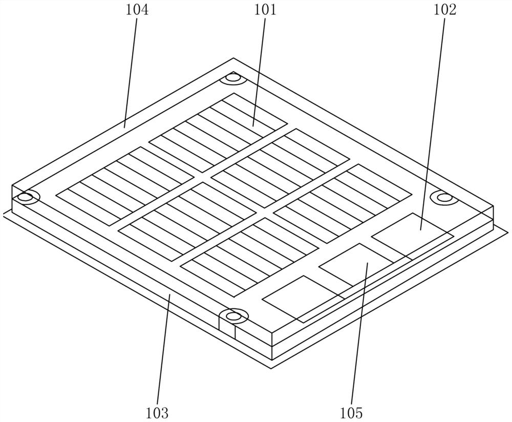
[0023] Such as figure 1 As shown, a photovoltaic module based on a diffractive optical element according to the present invention includes a heat-conducting substrate 103, on which a plurality of gallium arsenide chips 101 are arranged, and a plurality of gallium arsenide chips 101 are sequentially connected in series to form a conversion module, And the conversion module is covered with a diffractive optical element 104; the heat-conducting substrate 103 is provided with the positive and negative terminals 102 of the conversion module; the conversion module composed of several gallium arsenide chips 101 can perform laser light energy Efficient conversion, the diffractive optical element 104 is used to replace the traditional glass cover, the diffractive optical element 104 can scatter the laser light so that the gallium arsenide chip...


PUM

PropertyMeasurementUnit
transmittivityaaaaaaaaaa

Abstract

The invention relates to the technical field of photovoltaic power generation, in particular to a photovoltaic module based on a diffractive optical element. The photovoltaic module comprises a heat conductive substrate, wherein a plurality of gallium arsenide chips are arranged on the heat conductive substrate, and the plurality of gallium arsenide chips are sequentially connected in series to form a conversion module, and a diffractive optical element covers the conversion module; and the heat conductive substrate is provided with the positive and negative binding posts of the conversion module. The photovoltaic module based on a diffractive optical element is reasonable in structure, the gallium arsenide chips are connected in series and combined in a special arrangement mode to maximize utilization of the laser energy while maintaining the consistency of each chip and improve the stability of the gallium arsenide photovoltaic module; and moreover, the diffractive optical element (DOE) plated with an antireflection film with the wavelength of 800nm-850nm is adopted to replace a traditional glass cover plate on the photovoltaic chip, wherein a quartz material in the central region is doped with metal elements to scatter the laser light to have the uniform light intensity effect and improve the actual photoelectric conversion efficiency of the gallium arsenide chips.

Description

technical field [0001] The invention relates to the technical field of photovoltaic power generation, specifically refers to a photovoltaic module based on a diffractive optical element, and discloses a manufacturing method of a photovoltaic module based on a diffractive optical element. Background technique [0002] Laser energy supply technology is based on laser energy transmission and conversion technology, and laser has the characteristics of small beam emission angle and high energy density, and the energy loss is small during transmission, which is suitable for energy transmission in isolated spaces. The transmitting equipment with the laser as the core and the receiving equipment with the photovoltaic cell as the core have a small caliber, a fairly simple structure, and are easy to install and maintenance-free. At the same time, the laser energy transmission avoids electromagnetic interference to nearby electronic equipment during other isolated energy collection. ...

Claims


Application Information

Patent Timeline
Patent Type & Authority Patents(China)
IPC IPC(8): H01L31/05H02S40/00H02S40/22
CPCH01L31/0504H02S40/00H02S40/22Y02E10/52
Inventor 江翼张静刘正阳黄勤清周文张素香于春来陈佳许晓路李永祥符聪
Owner WUHAN NARI LIABILITY OF STATE GRID ELECTRIC POWER RES INST
Why Eureka
Eureka Blog
Learn More