
Optical antireflection structure, bottom emission electroluminescent device and preparation method

An electroluminescent device, bottom emission technology, applied in the direction of electrical components, semiconductor devices, circuits, etc., can solve the problems of low light extraction efficiency, low light extraction efficiency, loss, etc. good film effect

Active Publication Date: 2019-11-08
GUANGDONG JUHUA PRINTING DISPLAY TECH CO LTD
View PDF3 Cites 2 Cited by
  • Summary
  • Abstract
  • Description
  • Claims
  • Application Information

AI Technical Summary

Problems solved by technology

[0003] However, the light extraction efficiency of traditional bottom-emitting electroluminescent devices is very low. This is because the light is directly injected into the glass substrate from the anode layer with high refractive index, and then injected into the air from the glass substrate, and total reflection occurs at the two interfaces. And a lot of losses
It is estimated that about 60% of the light is captured by the interface of the anode layer / glass substrate, about 20% of the light is captured by the interface of the glass substrate / air, and only about 20% of the light can be transmitted, and the light extraction efficiency is very low

Method used


Image

  • Optical antireflection structure, bottom emission electroluminescent device and preparation method

Examples


Embodiment Construction

[0025] In order to facilitate the understanding of the present invention, the present invention will be described more fully below with reference to the associated drawings. Preferred embodiments of the invention are shown in the accompanying drawings. However, the present invention can be embodied in many different forms and is not limited to the embodiments described herein. On the contrary, these embodiments are provided to make the understanding of the disclosure of the present invention more thorough and comprehensive.

[0026] It should be noted that when an element is referred to as being “disposed on” another element, it may be directly on the other element or there may also be an intervening element. When an element is referred to as being "connected to" another element, it can be directly connected to the other element or intervening elements may also be present.

[0027] Unless otherwise defined, all technical and scientific terms used herein have the same meaning...


PUM


Abstract

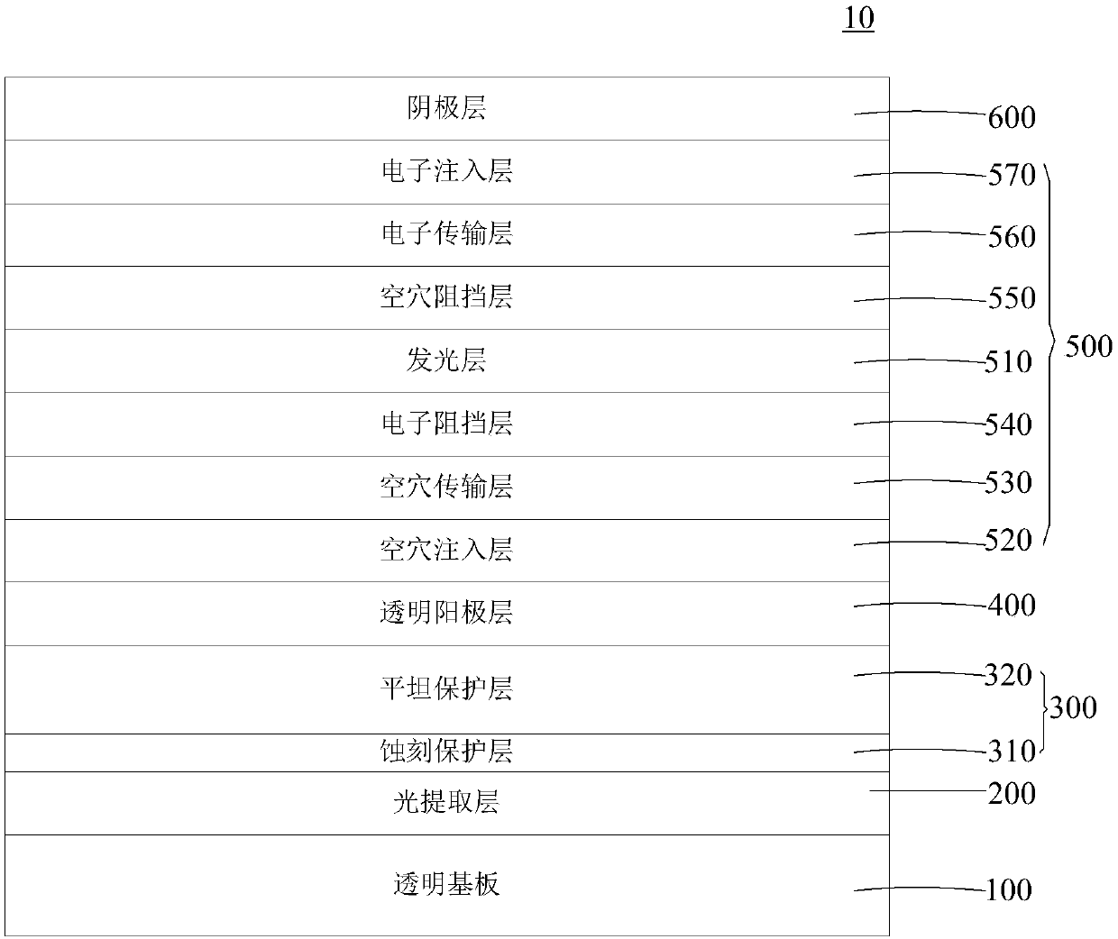
The invention relates to an optical antireflection structure, an electroluminescent device and a preparation method. The light extraction layer of the optical antireflection structure is prepared by aBi2O3 material which has a forbidden bandwidth of 2.8eV to 3eV, little absorption and high transmittance in a visible light region, and a high refractive index. For different preparation processes, the refractive index is generally from 1.8 to 2.2. When formed into a film, the Bi2O3 material is likely to form a rough surface where small particles protrude such that the surface of the light extraction layer has certain roughness. The particle protrusions of the rough surface can be used as a scattering unit to enhance the diffusion of light, reduce total reflection, and increase a light extraction rate. Therefore, the light extraction efficiency can be improved by inserting the Bi2O3 light extraction layer between a transparent anode layer and a transparent substrate. The Bi2O3 light extraction layer can be prepared by spin coating, magnetron sputtering or deposition, and is simple in process, low in cost is low, and good in film forming property.

Description

technical field [0001] The invention relates to the technical field of electroluminescence, in particular to an optical anti-reflection structure, a bottom emission electroluminescence device and a preparation method. Background technique [0002] OLED (Organic Light-Emitting Diode, Organic Light-Emitting Diode) and other electroluminescent devices are used in the new generation of mobile phone screens, computer monitors, Full-color TV and other fields have received widespread attention. Compared with traditional LCDs, this type of electroluminescent device does not require a backlight. When current passes through the organic functional layer, these organic materials can emit light, thereby greatly reducing the thickness and energy consumption of the display screen. [0003] However, the light extraction efficiency of traditional bottom-emitting electroluminescent devices is very low. This is because the light is directly injected into the glass substrate from the anode lay...

Claims


Application Information

Patent Timeline
Patent Type & Authority Applications(China)
IPC IPC(8): H01L33/02H01L33/20H01L33/38H01L33/00
CPCH01L33/005H01L33/02H01L33/20H01L33/38
Inventor 刘新
Owner GUANGDONG JUHUA PRINTING DISPLAY TECH CO LTD
Learn More