
Electric connector and method for manufacturing same

A technology for electrical connectors and manufacturing methods, which is applied in the field of electrical connectors and its manufacturing, and can solve problems such as reducing the transmission rate of signal terminals, the connection of insulating bodies is not firm, and the terminal row deviates from the predetermined position, etc.

Inactive Publication Date: 2019-11-08
DEYI PRECISION ELECTRONIC IND CO LTD PANYU
View PDF1 Cites 3 Cited by
  • Summary
  • Abstract
  • Description
  • Claims
  • Application Information

AI Technical Summary

Problems solved by technology

It is widely used in a variety of electrical circuits, and plays the role of connecting or disconnecting current or signals, while the existing electrical connector structure generally includes a terminal block and an insulating body embedded and formed on the terminal block , but in the process of embedded molding, the terminal block is easily affected by the impact of the liquid insulating material and deviates from the predetermined position, which leads to the weak connection between the terminal block and the injection-molded insulating body. In order to solve the above problems, technicians in this industry generally An auxiliary support foot connected to the side edge of the terminal row is added to the terminal row formed by stamping to further strengthen the fixing between the terminal row and the insulating body. For example, the Chinese patent with the notification number CN201690022U discloses a connector terminal support structure, such as figure 1 As shown, there are auxiliary support feet 34 on the two outermost terminals among the terminals, and support pins 33 connected with the auxiliary support feet 34 extend inwardly on the support frame, and the support pins 33 and the auxiliary support feet There is a breaking line 31 between 34, and the supporting pin 33 is formed in advance. When the plastic seat and the terminal are assembled, the supporting pin 33 can be broken off, but the above-mentioned technology has the following disadvantages: first, the auxiliary supporting pin 34 is due to the The outermost terminals are connected together. After an insulating body is injection-molded on the terminal and the bracket is removed, the auxiliary support feet 34 will always be connected to the outermost terminal and embedded in the insulating body together, so that Equivalent to an increase in the width of the outer terminal, it is easy to reduce the transmission rate of the signal terminal in actual use, so that the electrical connector cannot achieve high-frequency performance

Method used


Image

  • Electric connector and method for manufacturing same
  • Electric connector and method for manufacturing same
  • Electric connector and method for manufacturing same

Examples


no. 1 example

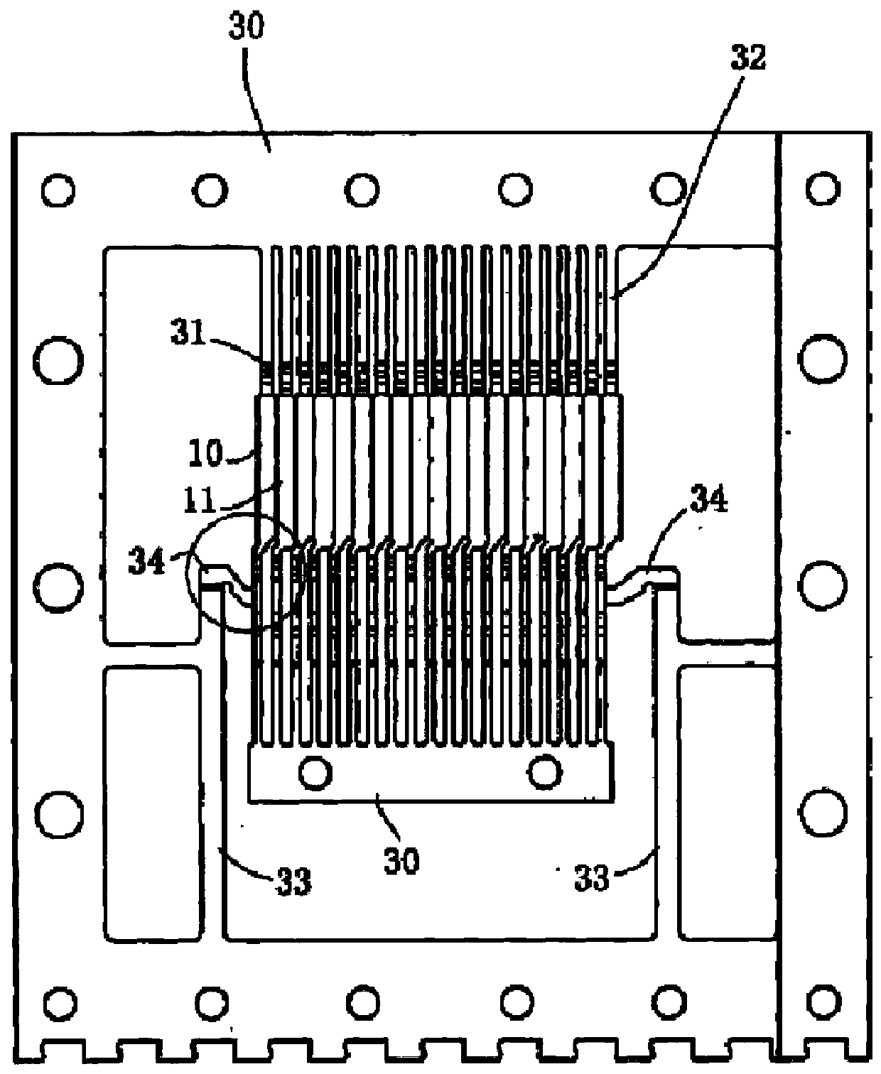
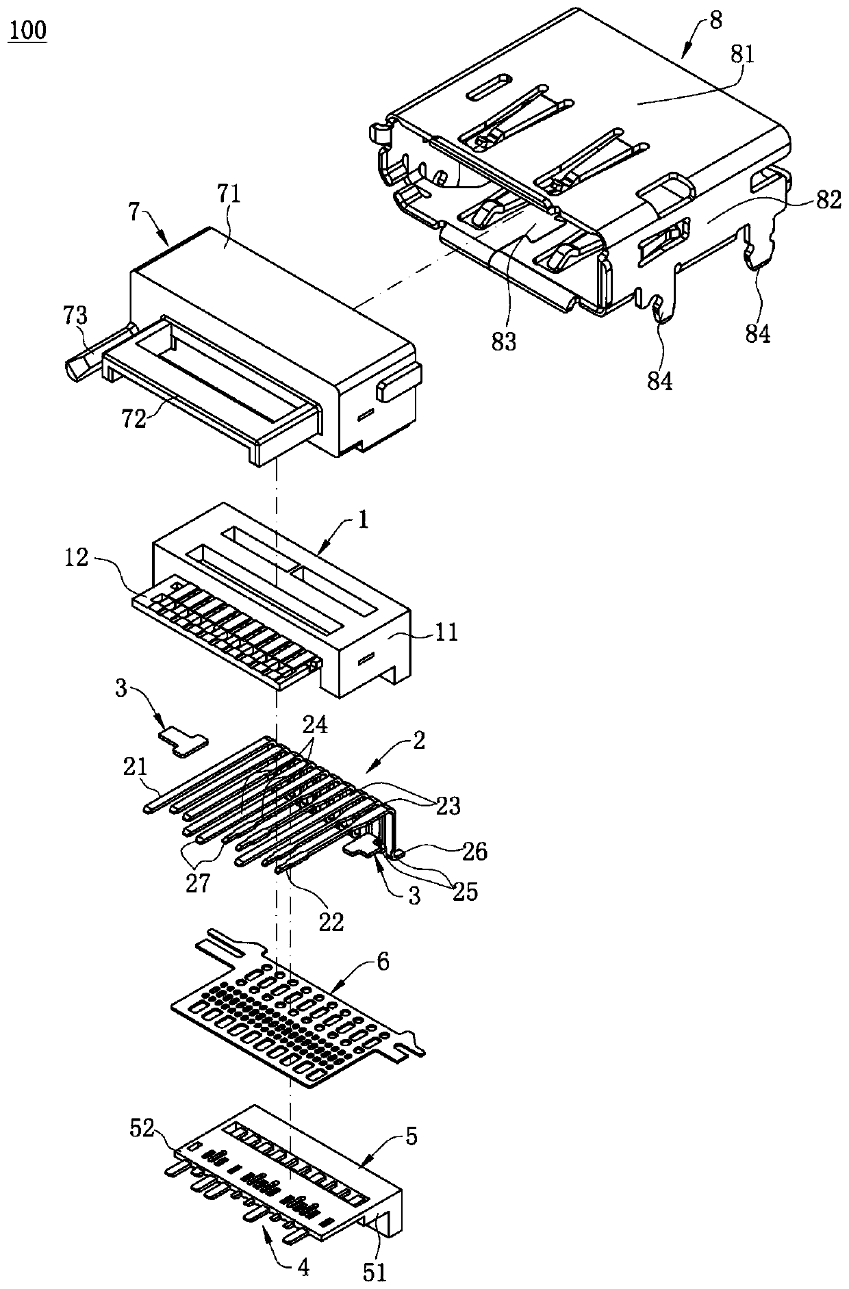
[0047] Such as figure 2 Shown is the first embodiment of the present invention: an electrical connector 100 for installing on a circuit board (not shown) to transmit high-frequency signals, the electrical connector 100 is a DP electrical connector, The electrical connector 100 mainly includes a first terminal row 2 embedded in an insulating body 1, a connector 3 and a shielding sheet 6, a second terminal row 4 embedded in an insulating seat 5, An insulating shell 7 formed on the insulating body 1 and the insulating base 5 and a shielding shell 8 wrapped on the insulating shell 7 .

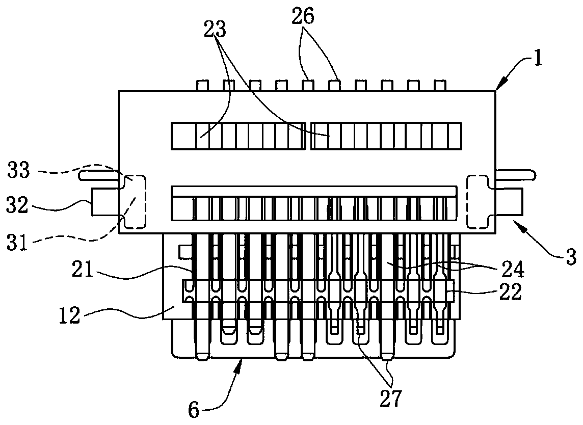
[0048] Specifically, such as image 3 with 4 As shown, the insulating body 1 is mainly made of plastic material and includes a rectangular base 11 and a first tongue 12 extending forward from the front end of the base 11. The insulating body 1 is injection molded The way is molded on the first terminal row 2 .

[0049] Such as figure 2 , image 3 , Figure 4 As shown, the first terminal bl...


PUM


Abstract

The invention discloses an electric connector and a method for manufacturing the same. A connecting member is embedded between the side edge of an insulating body and the outer side of the first terminal or last terminal in a first terminal strip, and a gap is arranged between the connecting member and the first terminal or last terminal, namely, the connecting member is not in contact with the adjacent first terminal or last terminal such that the width of the first terminal or last terminal cannot be increased. Therefore, the high-frequency transmission rate of the first terminal strip is ensured so that the electric connector can be formed which cannot affect the transmission quality of the terminals, is easy to machine and stable in structure, and has high-frequency transmission performance.

Description

【Technical field】 [0001] The invention relates to an electrical connector and a manufacturing method thereof, in particular to an electrical connector suitable for high-frequency transmission and a manufacturing method thereof. 【Background technique】 [0002] Electrical connectors are mainly used to bridge two conductors on a circuit so that current or signals can flow from one conductor to another conductor. It is widely used in a variety of electrical circuits, and plays the role of connecting or disconnecting current or signals, while the existing electrical connector structure generally includes a terminal block and an insulating body embedded and formed on the terminal block , but in the process of embedded molding, the terminal block is easily affected by the impact of the liquid insulating material and deviates from the predetermined position, which leads to the weak connection between the terminal block and the injection-molded insulating body. In order to solve the ...

Claims


Application Information

Patent Timeline
IPC IPC(8): H01R13/405H01R13/6591H01R43/24
CPCH01R13/405H01R13/6591H01R43/24H01R12/727H01R13/6474H01R13/6596H01R24/60H01R2107/00H01R13/504H01R13/646H01R13/6585H01R43/16
Inventor 蔡伦隆权秦大争
Owner DEYI PRECISION ELECTRONIC IND CO LTD PANYU
Learn More