Nursing bed for pregnant woman
A technology for nursing beds and pregnant women, which is applied in the field of nursing beds and can solve the problems of abdominal protection for pregnant women.
- Summary
- Abstract
- Description
- Claims
- Application Information
AI Technical Summary
Problems solved by technology
Method used
Image


Examples
specific Embodiment approach 1
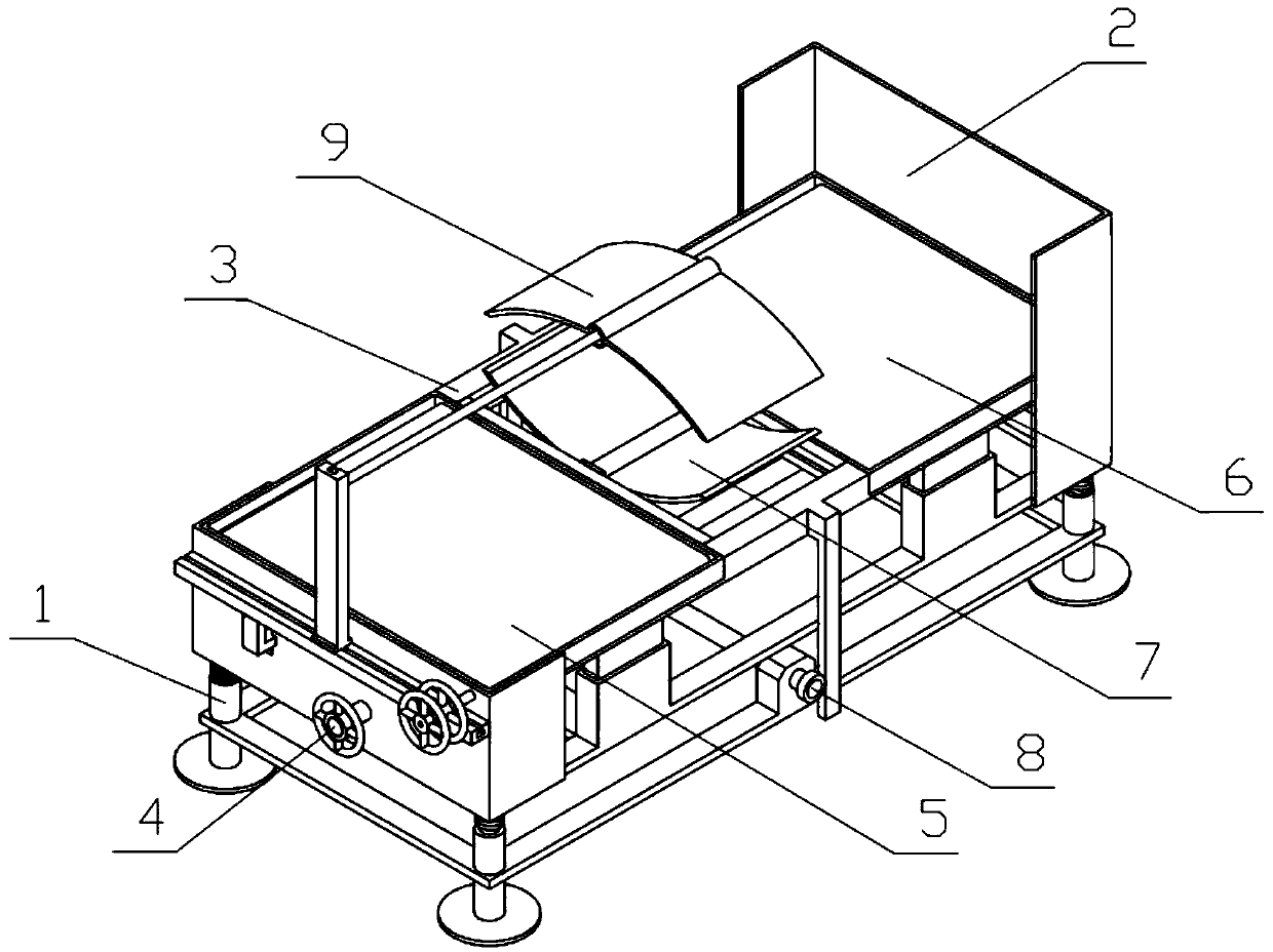
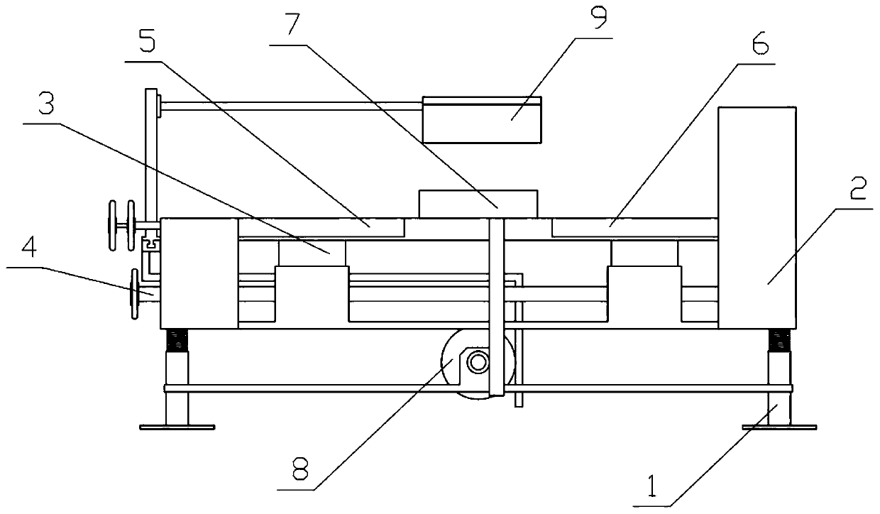
[0038] Combine below Figure 1-15Describe this embodiment, a nursing bed for pregnant women, including a supporting base 1, a lifting base 2, a mounting frame 3, a worm 4, a lateral movement mechanism I5, a lateral movement mechanism II6, a rotating guard plate 7, an amplification mechanism 8 and a protection mechanism 9. The lifting chassis 2 is slidably connected to the supporting chassis 1, a compression spring is fixedly connected between the supporting chassis 1 and the lifting chassis 2, the installation frame 3 is slidably connected to the supporting chassis 1, and the lifting chassis 2 The upper rotation is connected with a rotating threaded cylinder 2-4, the mounting frame 3 is provided with a threaded rod 3-3, the threaded rod 3-3 is threaded in the rotating threaded cylinder 2-4, and the lifting chassis 2 is rotatably connected with a worm 4 , the worm 4 and the rotating threaded barrel 2-4 are connected by transmission, the left and right sides of the mounting fram...
specific Embodiment approach 2
[0040] Combine below Figure 1-15 This embodiment will be described. This embodiment will further describe Embodiment 1. The support base 1 includes a support base 1-1 and a support foot 1-2. The four corners of the support base 1-1 are fixedly connected with Support feet 1-2.
specific Embodiment approach 3
[0042] Combine below Figure 1-15 Describe this embodiment, this embodiment will further explain the second embodiment, the lifting chassis 2 includes a lifting bottom frame 2-1, a sliding frame 2-2, a connecting plate I2-3, a turbine 2-5, and a supporting plate I2 -6, support plate II 2-7, sliding hole 2-8 and sliding column 2-9, the sliding frame 2-2 is fixedly connected to the lifting bottom frame 2-1, and the connecting plate I2 is fixedly connected to the lifting bottom frame 2-1 -3, the connecting plate I2-3 is rotatably connected with a rotating threaded cylinder 2-4, the rotating threaded cylinder 2-4 is fixedly connected with a turbine 2-5, and the front and rear ends of the lifting bottom frame 2-1 are respectively fixedly connected with support plates Ⅰ2-6 and the support plate Ⅱ2-7, the support plate Ⅱ2-7 is provided with sliding holes 2-8, the four corners of the lifting bottom frame 2-1 are fixedly connected with sliding columns 2-9, and the four sliding columns ...
PUM
 Abstract
Description
Claims
Application Information
 - R&D
- Intellectual Property
- Life Sciences
- Materials
- Tech Scout
- Unparalleled Data Quality
- Higher Quality Content
- 60% Fewer Hallucinations
Browse by: Latest US Patents, China's latest patents, Technical Efficacy Thesaurus, Application Domain, Technology Topic, Popular Technical Reports.
© 2025 PatSnap. All rights reserved.Legal|Privacy policy|Modern Slavery Act Transparency Statement|Sitemap|About US| Contact US: help@patsnap.com