
Turn-milling fixture for processing rotor

A rotor, turning and milling technology, applied in the direction of manufacturing tools, metal processing equipment, metal processing machinery parts, etc., can solve the problems of clamping and positioning errors, substandard processing accuracy and processing quality, waste of processing time and efficiency, etc., to achieve The effect of solving the resonance problem

Pending Publication Date: 2019-11-12
JIANGSU ZHENJIANG NEW ENERGY EQUIP
View PDF0 Cites 0 Cited by
  • Summary
  • Abstract
  • Description
  • Claims
  • Application Information

AI Technical Summary

Problems solved by technology

[0003] However, there are many processing disadvantages in the existing processing technology, mainly: 1. Separate processing of multiple processes will cause errors in clamping and positioning; 2. The safety of multiple lifting and handling of large workpieces; 3. Processing time and efficiency 4. The processing accuracy and processing quality are not up to standard

Method used


Image

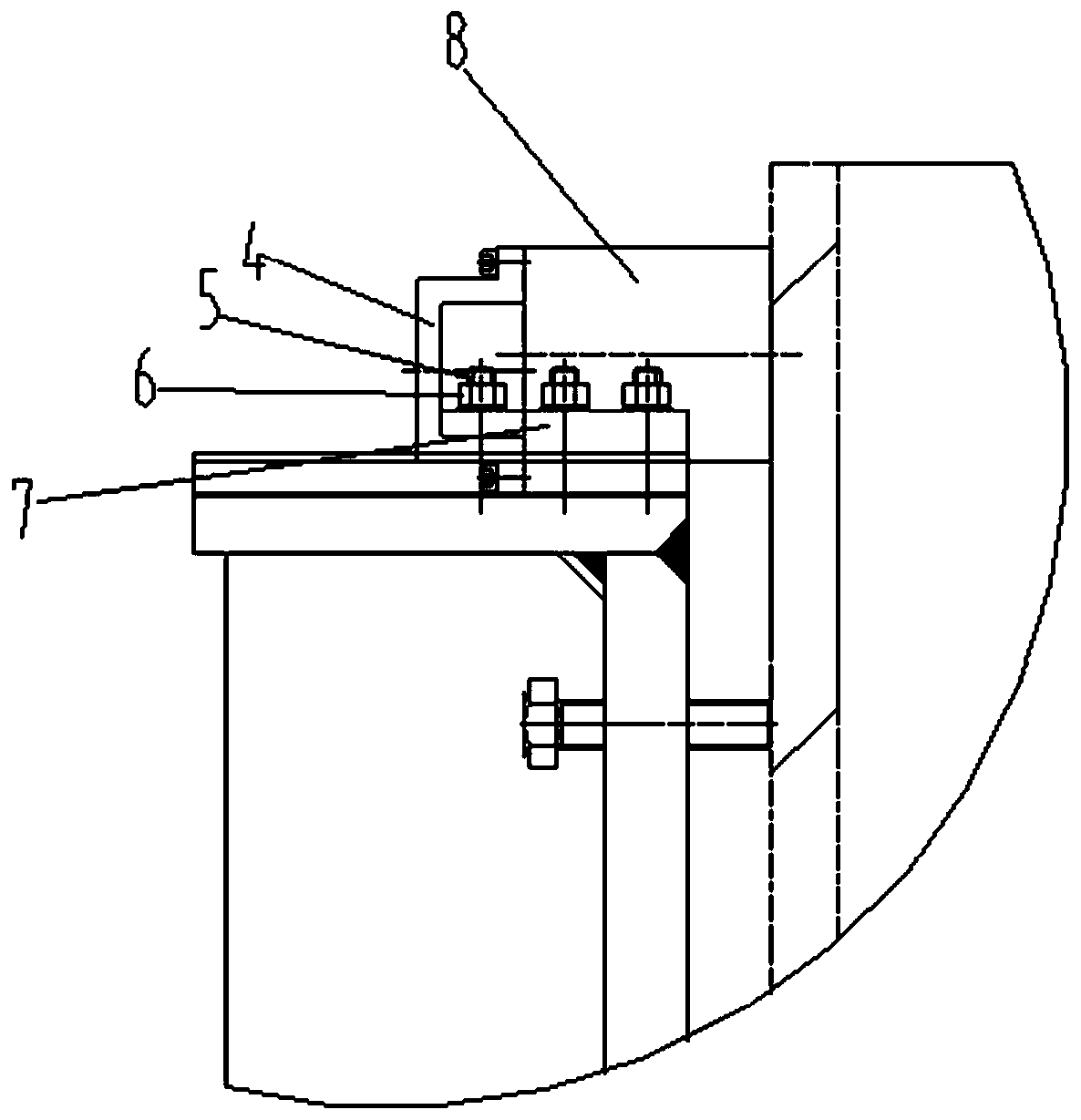
  • Turn-milling fixture for processing rotor
  • Turn-milling fixture for processing rotor

Examples


Embodiment Construction

[0019] The present invention is described in further detail now in conjunction with accompanying drawing. These drawings are all simplified schematic diagrams, which only illustrate the basic structure of the present invention in a schematic manner, so they only show the configurations related to the present invention.

[0020] like figure 1 As shown, the present invention is a turning and milling fixture for processing rotors, including a turning and milling table 1 on which a rotor 9 is placed, an outer cylinder 3 and an electromagnetic chuck 8, and at least There are two screw jacks 11, which are convenient for fixing and disassembling the rotor 9; the outer cylinder body 3 is detachably installed on the turning and milling workbench 1, and is kept relatively fixed by fastening bolts 12 and the turning and milling workbench 1, and the rotor 9 can be It is disassembled and connected to the outer cylinder 3, and the support bolts 10 are kept relatively fixed with the outer c...


PUM


Abstract

The invention discloses a turn-milling fixture for processing a rotor. The turn-milling fixture for processing the rotor comprises a turn-milling working table, an outer cylinder and an electromagnetic chuck. The outer part of a large cylinder of the rotor is mainly supported through the outer cylinder, so that the rigidity of the large cylinder of the rotor is improved, the production of resonance is prevented in the T-shaped groove milling process, and the aim of improving the processing efficiency, the processing precision and the surface quality is achieved; and meanwhile, the electromagnetic chuck fully sucks the large cylinder of the rotor, so that an effect on preventing the cylinder from deforming inwards or outwards when the T-shaped groove is turned and milled on the rotor is achieved.

Description

technical field [0001] The invention belongs to the technical field of wind power generator rotor processing and manufacturing, and in particular relates to a turning and milling fixture for processing rotors. Background technique [0002] The existing rotor processing technology generally uses vertical lathe for turning, and then CNC gantry milling for drilling; [0003] However, there are many processing disadvantages in the existing processing technology, mainly: 1. Separate processing of multiple processes will cause errors in clamping and positioning; 2. The safety of multiple lifting and handling of large workpieces; 3. Processing time and efficiency 4. The processing accuracy and processing quality are not up to standard. [0004] Therefore, in the rotor machining process, firstly, consider the type of machine tool, and then determine the clamping method on the machine tool. At the same time, you must also consider its reasonable tooling and fixtures, so as to comple...

Claims


Application Information

Patent Timeline
Patent Type & Authority Applications(China)
IPC IPC(8): B23Q3/06B23Q3/154
CPCB23Q3/062B23Q3/1543
Inventor 徐建华胡震
Owner JIANGSU ZHENJIANG NEW ENERGY EQUIP
Learn More