Conveying device

A transmission device and conveyor belt technology, applied in the direction of conveyor control devices, conveyors, conveyor objects, etc., can solve the problems of disassembly and assembly of the drive mechanism, and achieve the effect of changing the direction of transmission

Pending Publication Date: 2019-11-12
XINHAI IND BELTING
View PDF0 Cites 2 Cited by
  • Summary
  • Abstract
  • Description
  • Claims
  • Application Information

AI Technical Summary

Problems solved by technology

[0003] In order to overcome the deficiencies of the prior art, the object of the present invention is to disclose a conveying device to solve the problem of troublesome disassembly and assembly of the drive mechanism when the conveying direction of the article needs to be changed in the existing conveying device

Method used


Image

  • Conveying device
  • Conveying device
  • Conveying device

Examples


Embodiment Construction

[0032] Below, the present invention will be further described in conjunction with the accompanying drawings and specific implementation methods. It should be noted that, under the premise of not conflicting, the various embodiments described below or the technical features can be combined arbitrarily to form new embodiments. .

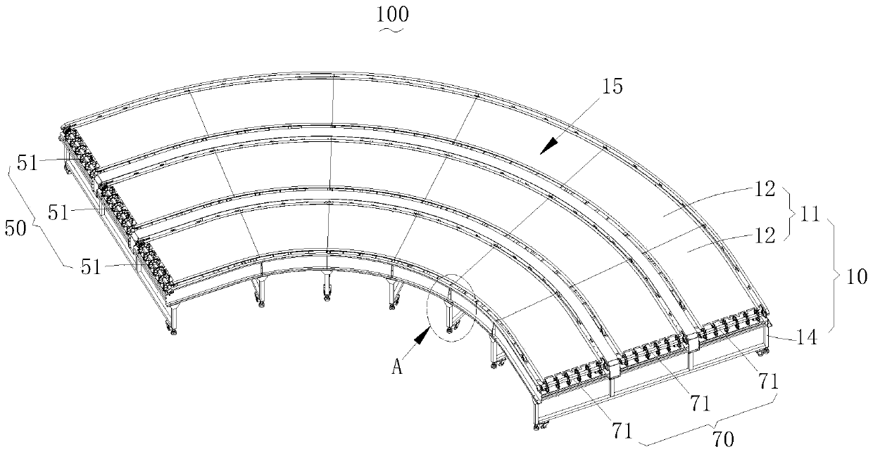
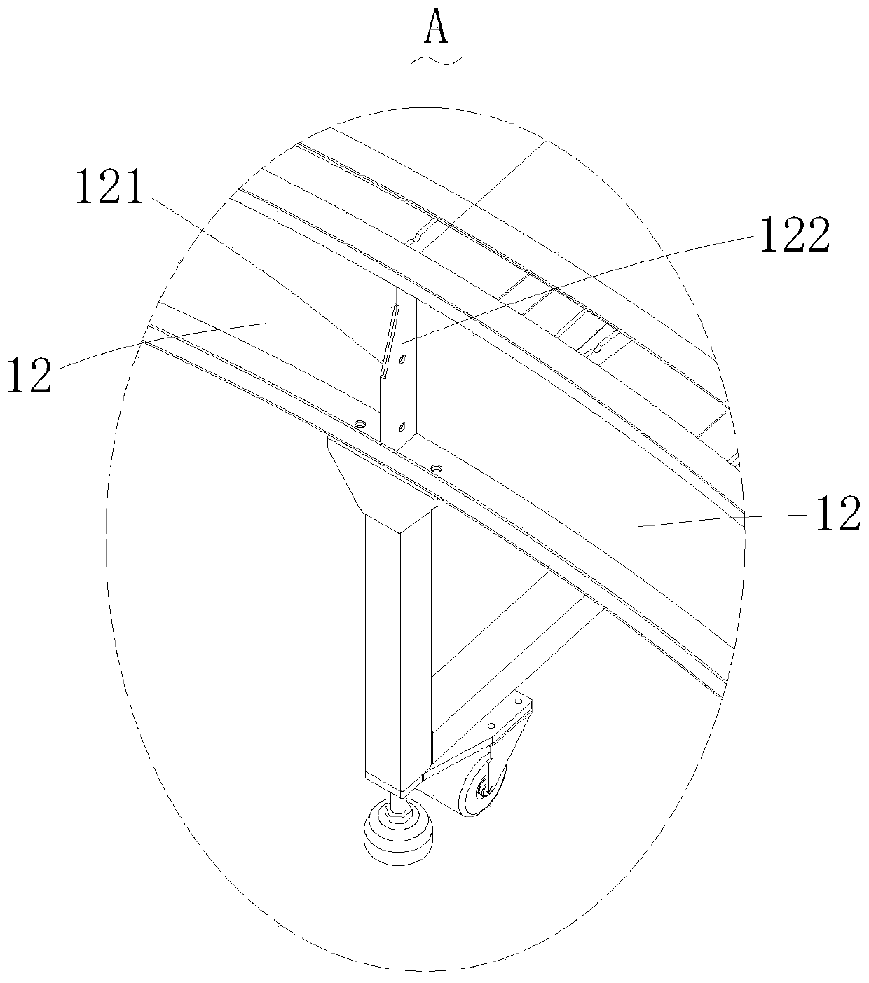
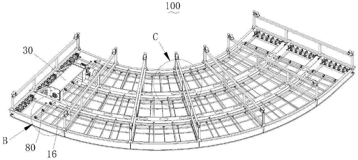
[0033] see Figure 1-9 , the embodiment of the present invention provides a curved conveyor device 100 for changing the conveying direction of articles, the curved conveyor device 100 includes a frame 10, a driving mechanism 30, a main rotating mechanism 50, an auxiliary rotating mechanism 70 and a conveyor belt ( not shown). The frame 10 is arc-shaped, the main rotating mechanism 50 is rotatably installed on one end of the frame 10, the auxiliary rotating mechanism 70 is rotatably installed on the other end of the frame 10, and the conveyor belt is wrapped around the frame 10, the main rotating mechanism 50 and the auxiliary rotating mechanism 70 Ab...


PUM


Abstract

The invention discloses a conveying device. The device comprises a machine frame, a plurality of conveying belts, a main rotating mechanism rotationally arranged at one end of the machine frame, an auxiliary rotating mechanism rotationally installed at the other end of the machine frame, and a driving mechanism installed on the machine frame and used for driving the main rotating mechanism to rotate, wherein the plurality of conveying belts are wound around the machine frame, the main rotating mechanism and the auxiliary rotating mechanism, the driving mechanism comprises a driving assembly arranged at the bottom of the machine frame and a plurality of transmission pairs which are in transmission connection between the driving assembly and the main rotating mechanism, the driving assemblyis detachably connected to the lower portion of one end of the machine frame, and a mounting structure for installing the driving assembly is reserved at the bottom of the other end of the machine frame. According to the conveying device, the driving assembly is detachably mounted on the machine frame, so that the driving assembly can be conveniently and integrally disassembled and mounted at theother end of the machine frame so as to change the conveying direction of the conveying belts.

Description

technical field [0001] The invention relates to the field of conveying equipment, in particular to a conveying device. Background technique [0002] Conveyor is a common part of conveyor belt system, mainly used to change the conveying direction of items on conveyor belt system. During the use of the conveying device, it is often necessary to change the conveying direction of the article, that is, to change the rotating direction of the conveyor belt. When the existing conveying device needs to change the conveying direction of the article, it is necessary to disassemble the drive assembly into several components, and then several The components are assembled one by one to the other end of the conveyor, which is very time-consuming and labor-intensive. Contents of the invention [0003] In order to overcome the deficiencies of the prior art, the object of the present invention is to disclose a conveying device to solve the problem of troublesome disassembly and assembly o...

Claims


Application Information

Patent Timeline
Patent Type & Authority Applications(China)
IPC IPC(8): B65G15/02B65G15/20B65G41/00B65G23/22B65G23/30B65G23/06B65G43/00B65G15/60B65G15/64
CPCB65G15/02B65G15/20B65G15/60B65G15/64B65G23/06B65G23/22B65G23/30B65G41/003B65G41/008B65G43/00
Inventor 洪健荣
Owner XINHAI IND BELTING
Why Eureka
Try Eureka