Flat plate flow cavity capable of simultaneously applying static pulling force and flow shearing force

A flat-plate flow chamber and shear force technology, which is applied in the field of flat-plate flow chambers, can solve the problems of reducing flow stability, expanding the cavity structure, and hindering various stimulation stresses, so as to improve the operation stability, improve the simulation effect, and reduce the The effect of running costs

Pending Publication Date: 2019-11-12
BEIHANG UNIV
View PDF2 Cites 2 Cited by
  • Summary
  • Abstract
  • Description
  • Claims
  • Application Information

AI Technical Summary

Problems solved by technology

As a result, the existing devices cannot truly simulate the corresponding growth environment and cannot meet the research needs
[0004] In addition, due to the high level of sterility required in the simulated environment for cell research, the conventional flat flow structures used to apply different stress stimuli cannot be combined with each other to achieve the effect of simultaneously applying multiple stress stimuli under the condition of ensuring the aseptic effect. , which increases the difficulty of applying multiple stimulus stre

Method used


Image

  • Flat plate flow cavity capable of simultaneously applying static pulling force and flow shearing force
  • Flat plate flow cavity capable of simultaneously applying static pulling force and flow shearing force

Examples


Embodiment Construction

[0028] The present invention will be further described below in conjunction with the accompanying drawings and embodiments, but not as a basis for limiting the present invention.

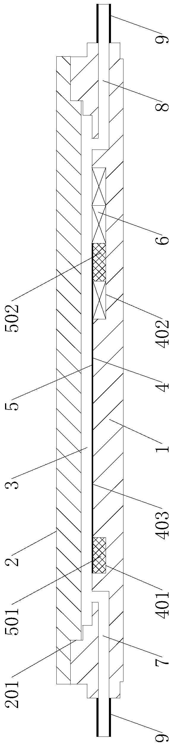
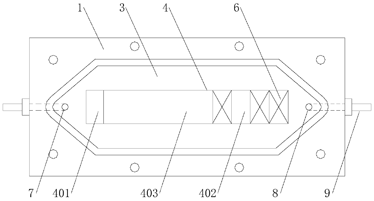
[0029] Example. A flat plate flow chamber that simultaneously applies static tension and flow shear, constituted as figure 1 As shown, it includes a base 1 and a cover plate 2 connected to each other. The base 1 is provided with a flow chamber groove 3, the bottom of the flow chamber groove 3 is provided with a placement groove 4, and the two ends of the placement groove 4 are respectively provided with a fixing groove 401 and a cover plate 2. The chute 402 is provided with a flexible film 5 in the placement groove 4, and one end of the flexible film 5 is provided with a first clip 501 buckled into the fixing groove 401, and the other end of the flexible film 5 is provided with a second clip snapped into the chute 402. The feet 502 , and a plurality of sliding blocks 6 are arranged in the sliding g...


PUM


Abstract

The invention discloses a flat plate flow cavity capable of simultaneously applying static pulling force and flow shearing force. The flow cavity comprises a base (1) and a cover plate (2) which are mutually connected, wherein a flow cavity groove (3) is arranged in the base (1); a placing groove (4) is arranged at the bottom of the flow cavity groove (3); two ends of the placing groove (4) are respectively provided with a fixing groove (401) and a sliding groove (402); a flexible film (5) is arranged in the placing groove (4); one end of the flexible film (5) is provided with a first clampingpin (501) buckled into the fixing groove (401); the other end of the flexible film (5) is provided with a second clamping pin (502) buckled into the sliding groove (402); and a plurality of the sliding blocks (6) are arranged in the sliding groove (402) at the outer side of the second clamping pin (502). The flow cavity can simultaneously load static traction force and flow shearing force on cells and adjust the loaded stress.

Description

technical field [0001] The invention relates to a flat-plate flow cavity, in particular to a flat-plate flow cavity which applies static tension and flow shear force simultaneously. Background technique [0002] Due to the complexity of the physiological structure of biological tissues and organs and the diversity of physiological environments in vivo, somatic cells are often in a complex mechanical environment and can be simultaneously subjected to various forms of mechanical stimulation including stretch stress and shear stress. ; and the biomechanical environment is of great significance for cells to carry out normal life activities and changes under pathological conditions. Therefore, it has become an important and routine research in the field of modern cell biomechanics to apply mechanical devices to cells cultured in vitro to simulate the stress stimulation of the in vivo environment. means. [0003] At present, the main device for studying the influence of stress on...

Claims


Application Information

Patent Timeline
IPC IPC(8): C12M3/00
CPCC12M23/26C12M23/50C12M25/02C12M29/18C12M35/04C12M37/04
Inventor 汲婧朱盟樊瑜波
Owner BEIHANG UNIV
Why Eureka
Try Eureka