Synchronous adjusting mechanism for furniture

A technology of synchronous adjustment and furniture, which is applied in the direction of building components, wing fan layout, building structure, etc., can solve the problems that large-shaped furniture cabinets cannot be widely used, shake up and down, and the storage space of the cabinet is limited. To achieve the effect of improving structural rationality and use stability, increasing connection strength and reducing force

Pending Publication Date: 2019-11-12
GUANGDONG DTC HARDWARE PRECISION MFG CO LTD
View PDF1 Cites 1 Cited by
  • Summary
  • Abstract
  • Description
  • Claims
  • Application Information

AI Technical Summary

Problems solved by technology

But the storage space of the cabinet part of this structure is limited, can not be widely used on the large-shaped furniture cabinet, if the above-mentioned structure is applied to the large-shaped furniture cabinet, then the size of the door body will be designed larger, and the size is smaller. The large door body is prone to swaying up and down due to its own weight during the opening and closing process, causing the door body and sliding components to be easily stuck or twisted during the opening and closing process, which cannot meet the needs of users

Method used


Image

  • Synchronous adjusting mechanism for furniture
  • Synchronous adjusting mechanism for furniture
  • Synchronous adjusting mechanism for furniture

Examples


no. 1 example

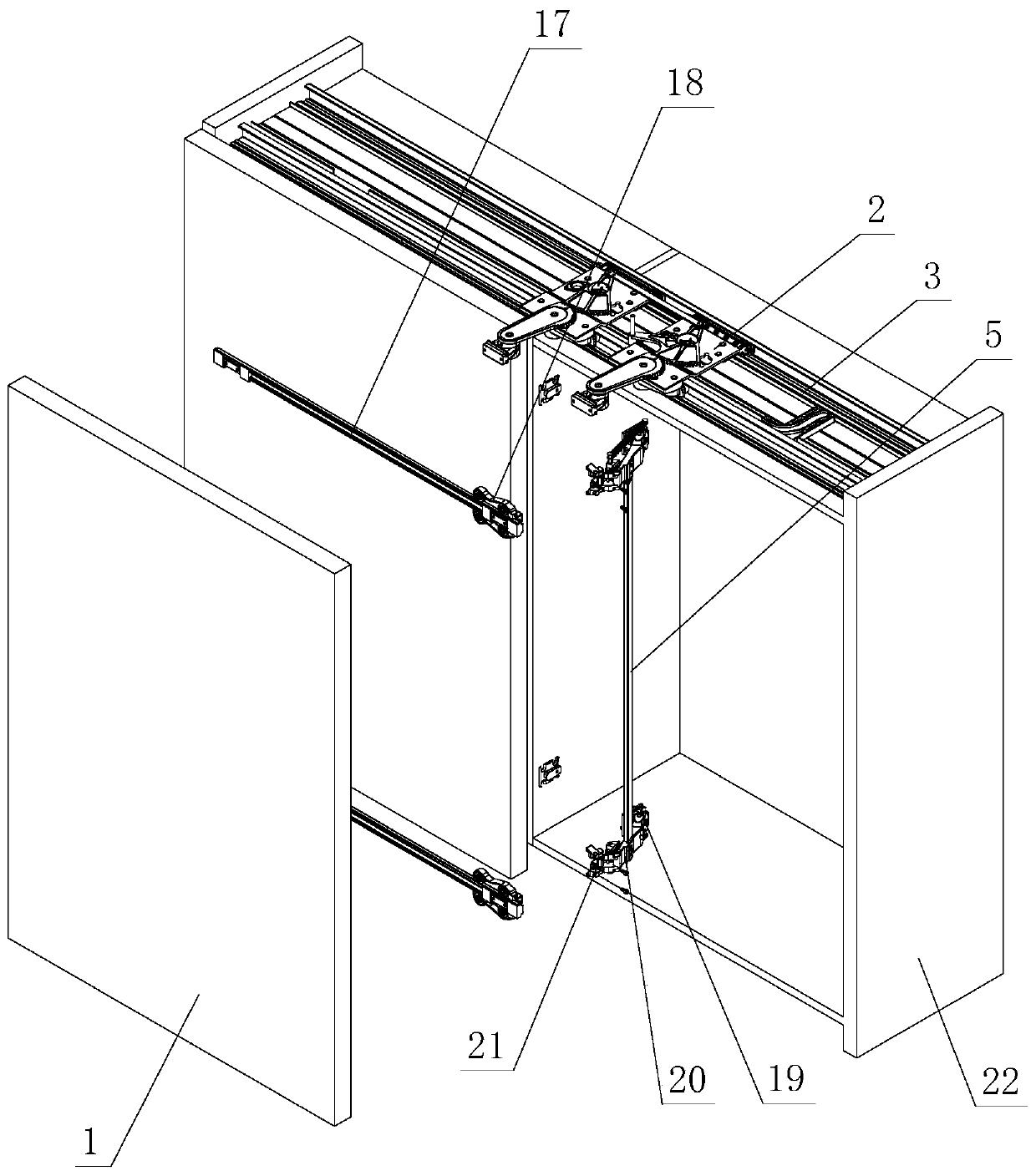
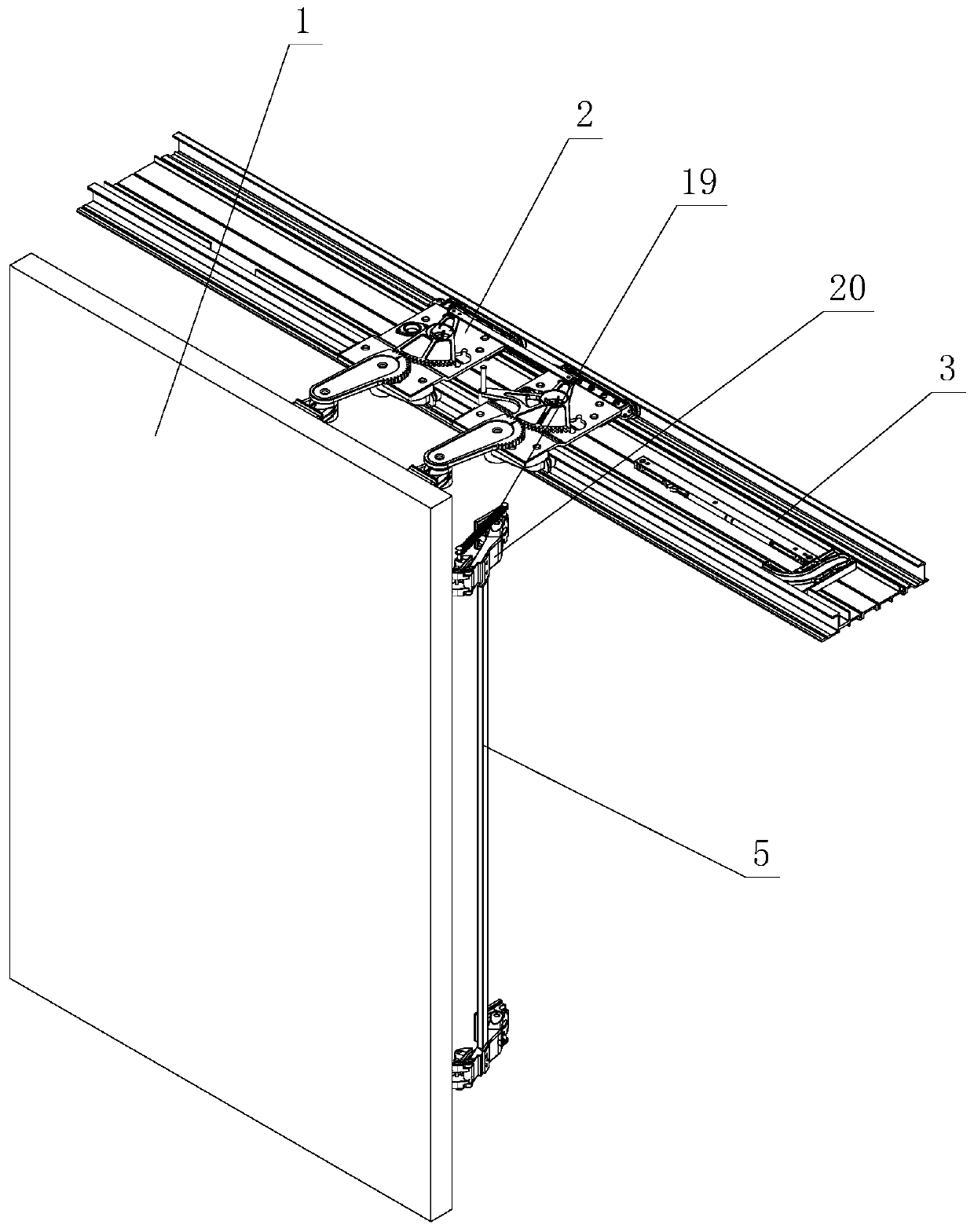
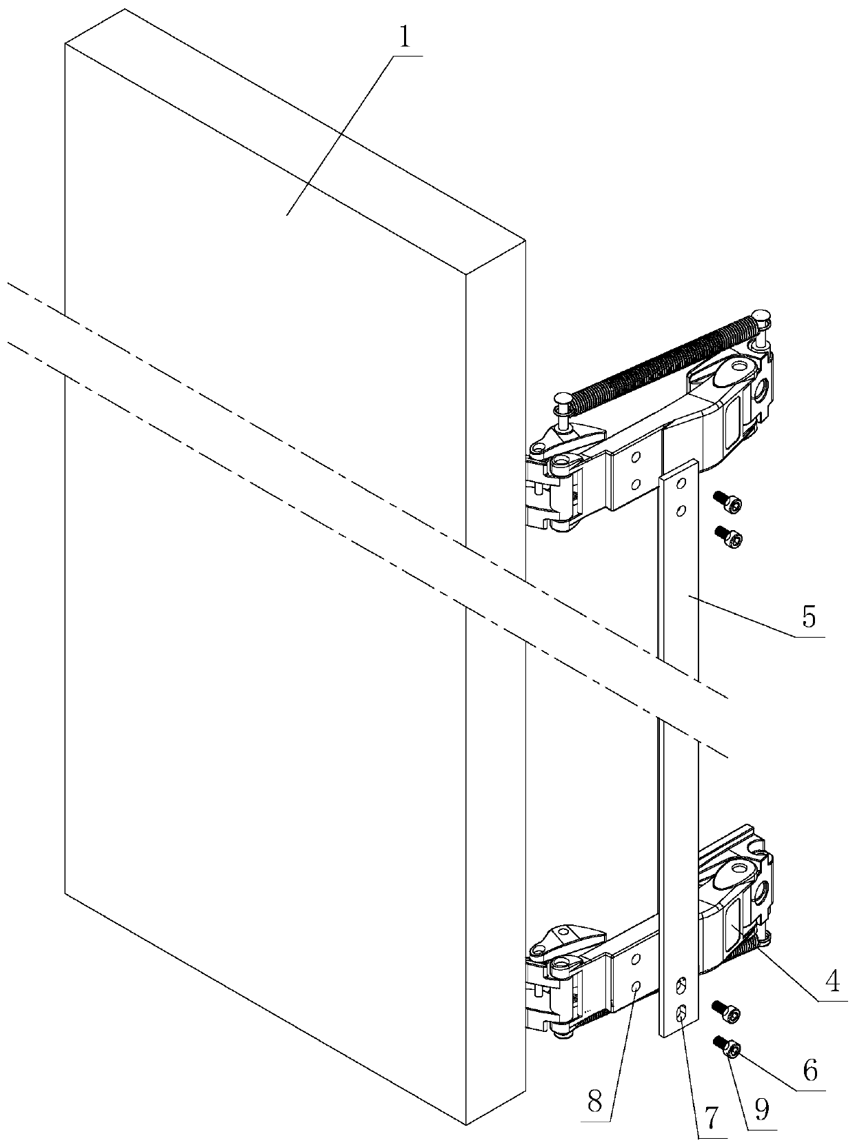
[0041] see Figure 1-Figure 4 , a synchronous adjustment mechanism for furniture, including a furniture door body 1, a sliding device 2, and a guide rail 3, the sliding device 2 is slidably arranged on the guide rail 3, and is connected with the furniture door body 1 in rotation or swing; the furniture door At least two hinge devices 4 are arranged on the body 1 to rotate or swing; the furniture door body 1 is opened and closed on the guide rail 3 through the cooperative activities of the sliding device 2 and the hinge device 4; wherein, at least two hinge devices 4 There is a synchronous lever 5 between them, and it rotates or swings synchronously on the furniture door 1 through the synchronous lever 5; an adjusting member is arranged on the synchronous lever 5, and / or between the synchronous lever 5 and the hinge device 4, synchronously The rod 5 moves on the hinge device 4 through the adjustment of the adjusting member, so as to adjust the relative position between the sync...

no. 2 example

[0052] see Figure 5 , Image 6 , this is a synchronous adjustment mechanism for furniture, which is different from the first embodiment in that: the adjustment part is provided with an adjustment part 6 .

[0053] The action part 6 is adjusted by a tool or manually, and the driving adjustment member moves between the synchronization rod 5 and at least two hinge devices 4, and the adjustment member locks or releases the connection between the synchronization rod 5 and at least two hinge devices 4 when it is active. Relative position, displacement occurs when the relative position between the synchronization rod 5 and at least two hinge devices 4 is released, so as to adjust the relative position between the synchronization rod 5 and the at least two hinge devices 4 .

[0054] There are at least two synchronous rods 5, at least two synchronous rods 5 are respectively positioned and connected with at least two hinge devices 4, and an intermediate moving part 10 is slidably arra...

no. 3 example

[0059] see Figure 7-Figure 9 , this is a synchronous adjustment mechanism for furniture, which is different from the first embodiment in that: the adjustment part is provided with an adjustment part 6 .

[0060] The action part 6 is adjusted by a tool or manually, and the driving adjustment part moves between the synchronization rod 5 and at least two hinge devices 4. The relative position between the synchronization rod 5 and at least two hinge devices 4 .

[0061] A connector 11 is fixedly arranged on the synchronous rod 5, and the movable guide part 7 is a threaded position and is arranged on the connector 11. The hinge device 4 is provided with a connecting part 8, or the movable guide part 7 is a threaded position and is arranged on the hinge. On the device 4, the connecting part 11 is provided with a connecting part 8; the adjusting part is a screw adjusting part 12, and is positioned and rotated on the thread position by the action of the adjusting part 6, and is driv...


PUM


Abstract

The invention relates to a synchronous adjusting mechanism for furniture. The synchronous adjusting mechanism includes a furniture door body, a sliding device, and a guide sliding rail, wherein the sliding device is slidably arranged on the guide sliding rail and is rotatably or asway connected with the furniture door body; the furniture door body is rotatably or asway provided with at least two hinge devices; the furniture door body is movably opened and closed on the guide sliding rail through matching of the sliding device and the hinge devices; a synchronous rod is arranged between the atleast two hinge devices, and the hinge devices rotate or swing synchronously on the furniture door body through the synchronous rod; and an adjusting part is arranged on the synchronous rod and / or between the synchronous rod and the hinge devices, and the synchronous rod moves on the hinge devices through adjustment of the adjusting part to adjust the relative position between the synchronous rodand the at least two hinged devices. Through the improved synchronous adjusting mechanism, the synchronous adjusting mechanism has the characteristics of being simple and reasonable in structure, reliable in performance, long in service life, quick and convenient in disassembly and assembly process, smooth and steady, unhindered and labor-saving in opening and closing process, low in manufacturingcost, easy to produce, easy to realize, safe and reliable and the like, and the practicability is high.

Description

technical field [0001] The invention relates to a synchronous adjustment mechanism for furniture. Background technique [0002] The Chinese patent literature number is CN2327260, which discloses a full-length mirror with a hidden storage cabinet on July 7, 1999. It has a cabinet part, and the rear wall and side walls of the cabinet form a space and a front opening. The door of the mirror cabinet is fixed on the cabinet with hidden hinges, and can cover the front opening of the cabinet, thus forming a mirror storage cabinet. When the cabinet door is closed, it is aligned with the cabinet, and it looks like a whole. The mirror storage cabinet is installed between two pillars on a base, and is rotatably fixed on the pillars so that the storage cabinet can be tilted. There is a tilt adjustment mechanism at a distance from the rotation point, which can adjust the relative position of the mirror storage cabinet. Based on the inclination angle of the support pillar, and maintained...

Claims


Application Information

Patent Timeline
Patent Type & Authority Applications(China)
IPC IPC(8): E06B3/50E05D15/06E05D7/04E05D7/12
CPCE05D7/0407E05D7/123E05D15/0626E05D2015/585E05Y2600/10E05Y2900/20E06B3/5054
Inventor 伍志勇
Owner GUANGDONG DTC HARDWARE PRECISION MFG CO LTD
Why Eureka
Try Eureka