Al technical title is built by PatSnap Al team. It summarizes the technical point description of the patent document.
A magnetorheological fluid, one-way damping technology, applied in vibration suppression adjustment, springs, shock absorbers, etc., can solve the problems of increasing the manufacturing cost of shock absorbers and increasing the amount of magnetorheological fluid, so as to reduce cost investment, reduce Dependence on the amount of magnetorheological fluid used and the effect of a small amount of use
Inactive Publication Date: 2019-11-12
JIANGSU UNIV
View PDF2 Cites 5 Cited by
Summary
Abstract
Description
Claims
Application Information
AI Technical Summary
This helps you quickly interpret patents by identifying the three key elements:
Problems solved by technology
Method used
Benefits of technology
Problems solved by technology
The patent with the application number 201610440467.7 invented a magneto-rheological fluid adjustable damping shock absorber. This kind of shock absorber can adjust the damping force to a certain extent, and improve the heat dissipation and installation and maintenance problems during work. However, it needs Filling the working cylinder with magnetorheological fluid requires more magnetorheological fluid, which increases the manufacturing cost of the shock absorber
Method used
Image
Click on the blue label to locate the original text in one second.
Reading with bidirectional positioning of images and text.
Examples
Embodiment Construction
[0016] Below in conjunction with accompanying drawing and specific embodiment the present invention is further described:
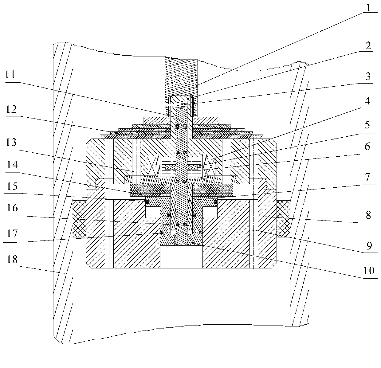
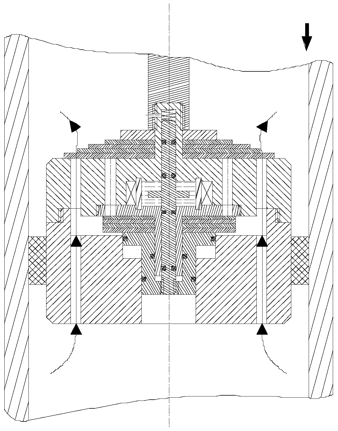
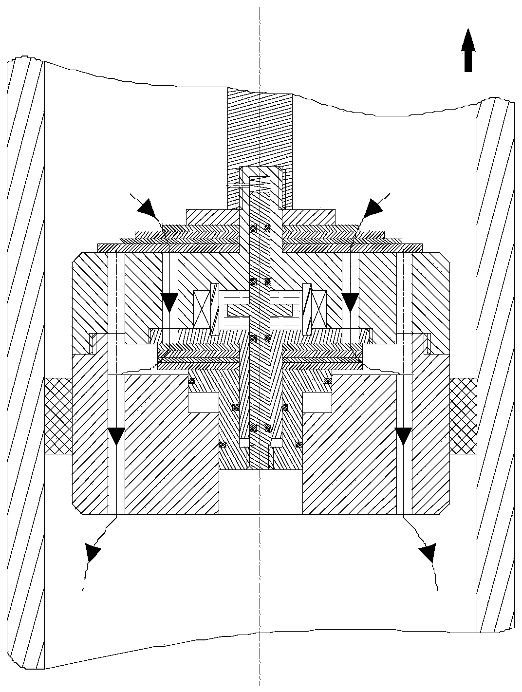
[0017] Such as figure 1 As shown, a magnetorheological fluid one-way damping regulating valve of the present invention specifically includes a piston rod 1, a squeeze valve body 2, a return spring 3, an excitation coil 4, a magnetorheological fluid 5, a magnetic isolation ring 6, Extrusion valve base 7, piston base 8, normal through hole A 9, movable bonnet 10, valve core 11, circulation valve group 12, normal through hole B 13, recovery valve group 14, sealing ring A 15, sealing ring B16, sealing ring C 17, working cylinder 18, etc. The lower end of the piston rod 1 is connected to the upper end of the extrusion valve body 2, and the lower end of the extrusion valve body 2 is connected to the upper end of the piston base 7 by threads; the valve core 11, the excitation coil 4, the magnetorheological fluid 5 and the magnetic isolation The ring 6 is packa...
PUM
Abstract
The invention discloses a magnetorheological fluid one-way damping regulation valve which mainly comprises a piston rod, a reset spring, a squeezing valve assembly, a movable valve cover, a circulation valve disc group, a rebound valve disc group, a piston base, a working cylinder and the like. The squeezing valve assembly comprises a valve element, a squeezing valve body, a squeezing valve base,a magnet exciting coil, a magnetorheological fluid and a magnetic isolating ring. The lower end of the piston rod and the upper end of the squeezing valve body are in threaded connection, the lower end of the valve element and the lower end of the movable valve cover are in threaded connection, and the lower end of the squeezing valve body and the upper end of the piston base are in threaded connection; and the valve element, the magnet exciting coil, the magnetorheological fluid and the magnetic isolating ring are encapsulated into the squeezing valve body through screw threads between the lower end of the squeezing valve body and the upper end of the squeezing valve base. In the recovery stroke, along with the increase of the electric current of the magnet exciting coil, the viscosity ofthe magnetorheological fluid is increased, the valve element drives the movable valve cover to move downwards, the suffered resistance is increased, the opening force of each valve disc is further increased, and a damping force and a current magnitude are changed in direct proportion. The magnetorheological fluid one-way damping regulation valve provided by the invention has the advantages of less magnetorheological fluid usage amount, fast dynamic response speed, simple structure and the like, the comfort and the controllability of vehicle driving are effectively improved, and the comfort inriding is greatly improved.
Description
technical field [0001] The invention relates to a magneto-rheological fluid damping regulating valve that can be used in the field of single-tube and double-tube shock absorbers, in particular to a magneto-rheological fluid unit for shock absorbers that can perform stepless adjustment of damping according to different working conditions. to the damping regulating valve. Background technique [0002] The shock absorber is an important damping element of the automobile suspension system. It is mainly used to absorb the shock and vibration generated during the driving of the vehicle. comfortability. The traditional non-adjustable damping shock absorber can no longer meet people's needs. In order to meet the needs of different road conditions, the research and development of adjustable damping shock absorber has been deepening in recent years. [0003] The patent with application number 201810247280.4 discloses a magnetorheological valve-controlled damping stepless adjustable ...
Claims
Application Information
Patent Timeline
Application Date:The date an application was filed.
Publication Date:The date a patent or application was officially published.
First Publication Date:The earliest publication date of a patent with the same application number.
Issue Date:Publication date of the patent grant document.
PCT Entry Date:The Entry date of PCT National Phase.
Estimated Expiry Date:The statutory expiry date of a patent right according to the Patent Law, and it is the longest term of protection that the patent right can achieve without the termination of the patent right due to other reasons(Term extension factor has been taken into account ).
Invalid Date:Actual expiry date is based on effective date or publication date of legal transaction data of invalid patent.