Program-control method for temperature control in quick flash annealing furnace

A technology of control area and furnace cavity, which is applied in the direction of temperature control, furnace control device, furnace, etc. using electric mode, can solve the problem of inability to realize rapid heat treatment function, etc., and achieves high integration, high adjustment accuracy, and simple control circuit. Effect

Inactive Publication Date: 2011-04-06
BEIJING ZHONGKEXIN ELECTRONICS EQUIP
View PDF0 Cites 4 Cited by
  • Summary
  • Abstract
  • Description
  • Claims
  • Application Information

AI Technical Summary

Problems solved by technology

[0002] With the shrinking of semiconductor technology from 130nm to less than 90nm, more and more logic devices are integrated on each chip, and there are more and more process steps for the ion implanter used as ion doping. After doping, it needs to use The rapid annealing system of the rapid annealing system requires an annealing efficiency of 45 to 70 pieces / hour, so the heating up and annealing time of the annealing must be increased. ℃ / second, the temperature control accuracy during the high temperature holding period can reach ±1.5℃, and the resistance uniformity after heat treatment can reach 1.5%. Based on these requirements, the traditional PID temperature adjustment control method can no longer realize the latest rapid heat treatment function

Method used


Image

  • Program-control method for temperature control in quick flash annealing furnace
  • Program-control method for temperature control in quick flash annealing furnace
  • Program-control method for temperature control in quick flash annealing furnace

Examples


Embodiment Construction

[0015] The present invention will be further described below in conjunction with the accompanying drawings.

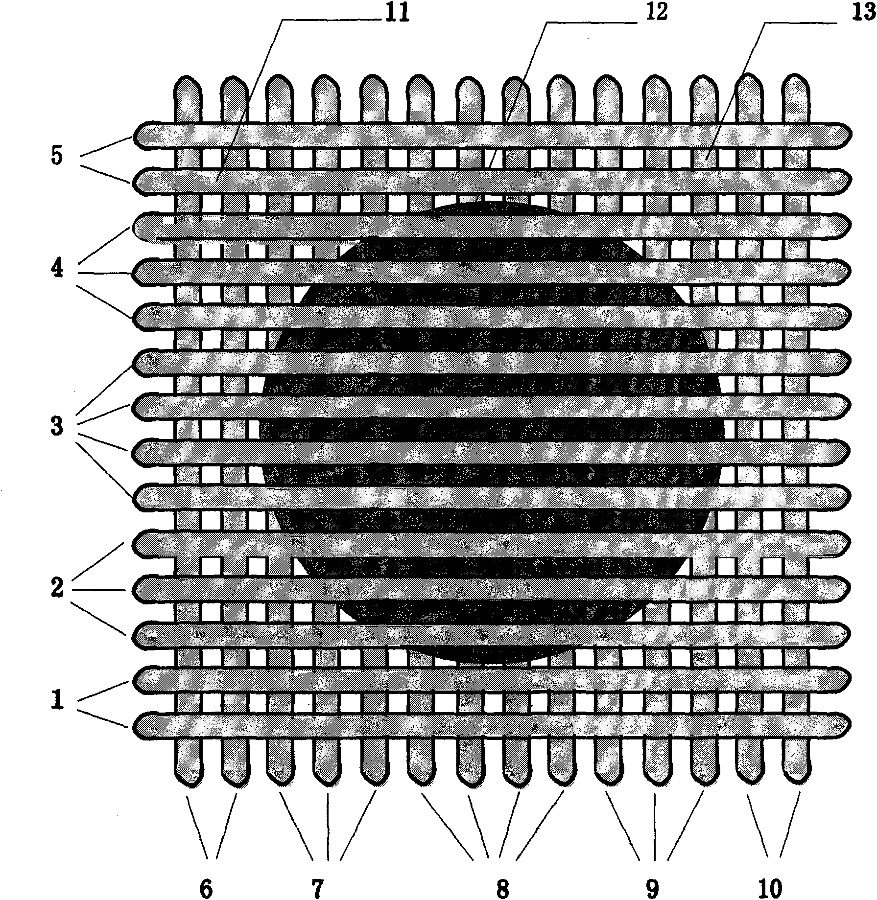
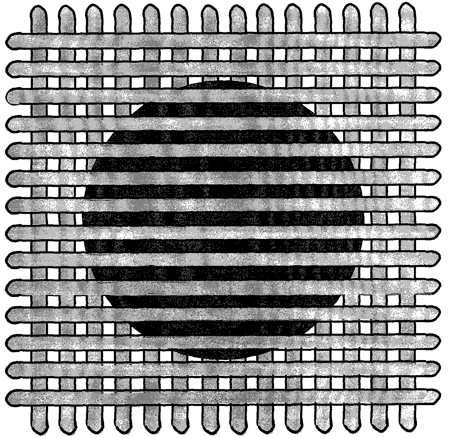
[0016] see figure 1 , the lamp tube layout of the rapid flash annealing furnace is described as follows: 1 is control area 1; 2 is control area 2; 3 is control area 3; 4 is control area 4; 5 is control area 5; 6 is control area 6; Control area 7; 8 is control area 8; 9 is control area 9; 10 is control area 10; 11 is the top lamp group; 12 is the silicon wafer; 13 is the bottom lamp group.

[0017] The heating of the silicon wafer adopts the halogen tungsten lamp radiation heating method. A total of 28 halogen lamp tubes of 1.5KW and 2KW specifications are used, which are respectively installed on the top and bottom of the furnace cavity, and each has 14 lamp tubes. The lamp tubes at the bottom are arranged in a vertical cross shape. The 28 lamp tubes are divided into 10 heating power control areas, and 5 heating power control areas are distributed on the top and bott...


PUM


Abstract

The invention discloses a novel program-control method for temperature control in a quick flash annealing furnace. The quick flash annealing furnace is process equipment of semiconductor industry, and belongs to the field of the manufacturing of semiconductor devices. Silicon wafers are heated by a radiation heating method of halogen tungsten lamps, 28 halogen lamp tubes with two specifications of 1.5 kilowatts and 2 kilowatts are respectively arranged on the top and at the bottom of a furnace chamber, wherein the 14 lamp tubes are arranged on the top, and the other 14 lamp tubes are arranged at the bottom; the lamp tubes on the top and at the bottom are arranged vertically and crosswise; the 28 lamp tubes are divided into 10 heating power control areas, and the 5 heating power control areas are distributed on the top and the other 5 heating power control areas are distributed at the bottom; and in order to ensure that the temperature of the silicon wafers in the heating and annealing process is uniform, the power and number of the lamp tubes in each heating power area are different, the lamp tubes in the heating power control areas on the top and at the bottom are distributed symmetrically, and the heating of the lamp tubes in each area is adjusted and controlled accurately according to an adaptive algorithm model so as to fulfill the aims that the silicon wafers in the furnace chamber are heated quickly and have the uniform temperature.

Description

technical field [0001] The invention realizes the temperature control through hardware design, and controls the power of the halogen lamp through an adaptive algorithm model, so as to improve the temperature uniformity of the silicon wafer and the working efficiency of the fast flash annealing furnace, and meet the requirements of the semiconductor process equipment of the integrated circuit manufacturing technology. The rapid development of the fast flash annealing furnace is a process equipment in the semiconductor industry, and the invention belongs to the field of semiconductor device manufacturing. Background technique [0002] With the shrinking of semiconductor technology from 130nm to less than 90nm, more and more logic devices are integrated on each chip, and the ion implanter used as ion doping has more and more process steps. After doping, it needs to use The rapid annealing system of the rapid annealing system requires an annealing efficiency of 45-70 pieces / hour...

Claims


Application Information

Patent Timeline
Patent Type & Authority Applications(China)
IPC IPC(8): F27D11/00F27D19/00G05D23/19H01L21/00
Inventor 金泽军伍三忠龙会跃姚琛易文杰
Owner BEIJING ZHONGKEXIN ELECTRONICS EQUIP
Why Eureka
Try Eureka