
A Method of Improving the Control Stability of Probe Automatic Tracking Measurement

A measurement control and automatic tracking technology, applied in sequence/logic controller program control, measurement device, electrical program control, etc., can solve the problems of single control method, limited displacement speed, long test period, etc. The effect of application range, increasing step speed and shortening test cycle

Active Publication Date: 2021-07-09
AECC SHENYANG ENGINE RES INST
View PDF7 Cites 0 Cited by
  • Summary
  • Abstract
  • Description
  • Claims
  • Application Information

AI Technical Summary

Problems solved by technology

[0027] a) Sensitivity is manually adjusted, and there are certain technical defects, such as large overshoot of process control (or low sensitivity and insensitive probe response), which will affect the measurement accuracy and is very inconvenient to use;
[0028] b) Due to the hardware inductive negative feedback control method, the control method is single, the probe fluctuation is greatly affected by the signal strength, and the system lacks an intelligent control method for sensitivity and overshoot, as well as a diagnostic function for qualified data and The means of reducing the fluctuation range of the probe. The probe will have a certain range of fluctuation during the measurement. This small fluctuation of the probe is not conducive to improving the measurement accuracy of the test system, and it is also not conducive to improving the measurement accuracy of the test system. The probe The fluctuation determines that the data collected by the probe is not suitable for the application of new data processing methods;
[0029] c) Due to the hardware negative feedback control system adopted, the steady-state accuracy of its control is poor, which limits the displacement speed, the test period is long, and the test cost is increased;
[0030] d) Since the fluctuation of the probe cannot be effectively controlled, the shock wave generated by the probe head will disturb the flow field under high Mach number conditions, which is unfavorable for flow field measurement

Method used


Image

  • A Method of Improving the Control Stability of Probe Automatic Tracking Measurement
  • A Method of Improving the Control Stability of Probe Automatic Tracking Measurement
  • A Method of Improving the Control Stability of Probe Automatic Tracking Measurement

Examples


Embodiment Construction

[0063] In order to make the purpose, technical solution and advantages of the application more clear, the technical solution in the embodiment of the application will be described in more detail below in conjunction with the drawings in the embodiment of the application. In the drawings, the same or similar reference numerals denote the same or similar elements or elements having the same or similar functions throughout. The described embodiments are some, but not all, embodiments of the application. The embodiments described below by referring to the figures are exemplary, and are intended to explain the present application, and should not be construed as limiting the present application. Based on the embodiments in this application, all other embodiments obtained by persons of ordinary skill in the art without creative efforts fall within the protection scope of this application. Embodiments of the present application will be described in detail below in conjunction with th...


PUM


Abstract

The application belongs to the technical field of gas flow field measurement, and particularly relates to a method for improving the stability of probe automatic tracking measurement control, including: calibrating the static zero point value of the differential pressure transmitter; Perform measurement; PLC collects the electrical signal of the differential pressure transmitter in real time and converts it into a pressure value. When the difference of the differential pressure transmitter in the vertical direction is less than or equal to the first predetermined value, the zero speed code is sent; otherwise, the calculation Obtain the real-time calibration pressure coefficient of the pitch angle and convert it into a speed control code; when the angular displacement speed of the probe is less than or equal to the second predetermined value, send the speed control code; otherwise, set the upper limit speed code of the probe. The method for improving the stability of probe automatic tracking measurement control of the present application solves the uncontrollable overshoot in the probe measurement process and the probe swing phenomenon during measurement, improves the stepping speed along the grid pitch (or blade height), shortens the Test cycle, reduce test cost.

Description

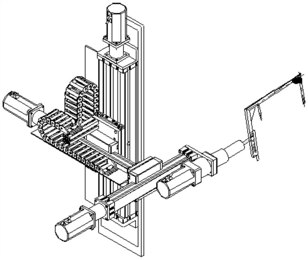
technical field [0001] The application belongs to the technical field of gas flow field measurement, and in particular relates to a method for improving the control stability of probe automatic tracking measurement. Background technique [0002] When measuring the flow field where the medium is gas, the measurement probe is usually installed on the displacement mechanism to measure the point, line and surface of the flow field space. The four-axis displacement mechanism (mechanism behind the gate) can be driven in the three directions of the orthogonal directions X, Y and Z, and there is another axis that can rotate freely to drive the probe to rotate along the probe axis, such as figure 1 As shown; the three-axis displacement mechanism (mechanism in front of the gate) can be driven in the two directions of the orthogonal directions X and Y, and there is another axis that can rotate freely to drive the probe to rotate along the probe axis. [0003] When measuring the flow f...

Claims


Application Information

Patent Timeline
Patent Type & Authority Patents(China)
IPC IPC(8): G01M9/06G05B19/05
CPCG01M9/06G05B19/05
Inventor 王东吴法勇梅繁郑南武卉刘建明
Owner AECC SHENYANG ENGINE RES INST
Learn More