
Retractable CT (Computerized Tomography) measuring rod and measuring method thereof

A telescopic, measuring rod technology, applied in the direction of measuring electrical variables, measuring electricity, measuring devices, etc., can solve the problems of easy tilting, low retraction and retraction efficiency, etc., and achieves the effect of small friction, improved retractable and retractable efficiency, and labor-saving lifting and lowering.

Pending Publication Date: 2019-11-12
KUYTUN POWER SUPPLYING CO STATE GRID XINJIANG ELECTRIC POWER CO
View PDF0 Cites 4 Cited by
  • Summary
  • Abstract
  • Description
  • Claims
  • Application Information

AI Technical Summary

Problems solved by technology

[0004] Aiming at the deficiencies of the prior art, the present invention provides a telescopic CT measuring rod and its measuring method, which solves the problems of easy inclination between rods and low retractable efficiency when traditional CT measuring rods are spliced ​​together.

Method used


Image

  • Retractable CT (Computerized Tomography) measuring rod and measuring method thereof
  • Retractable CT (Computerized Tomography) measuring rod and measuring method thereof
  • Retractable CT (Computerized Tomography) measuring rod and measuring method thereof

Examples


Embodiment Construction

[0027] The following will clearly and completely describe the technical solutions in the embodiments of the present invention with reference to the accompanying drawings in the embodiments of the present invention. Obviously, the described embodiments are only some, not all, embodiments of the present invention. Based on the embodiments of the present invention, all other embodiments obtained by persons of ordinary skill in the art without making creative efforts belong to the protection scope of the present invention.

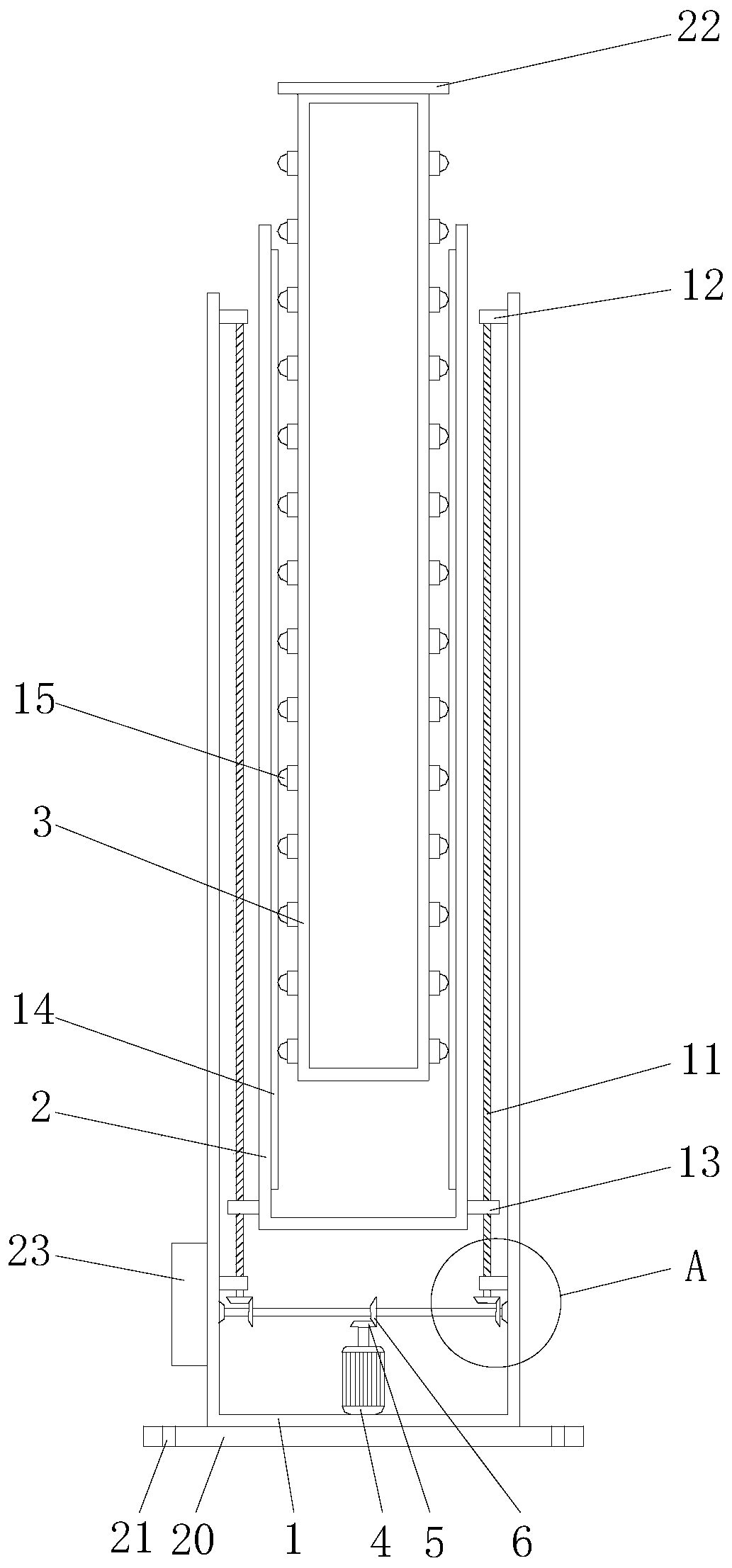
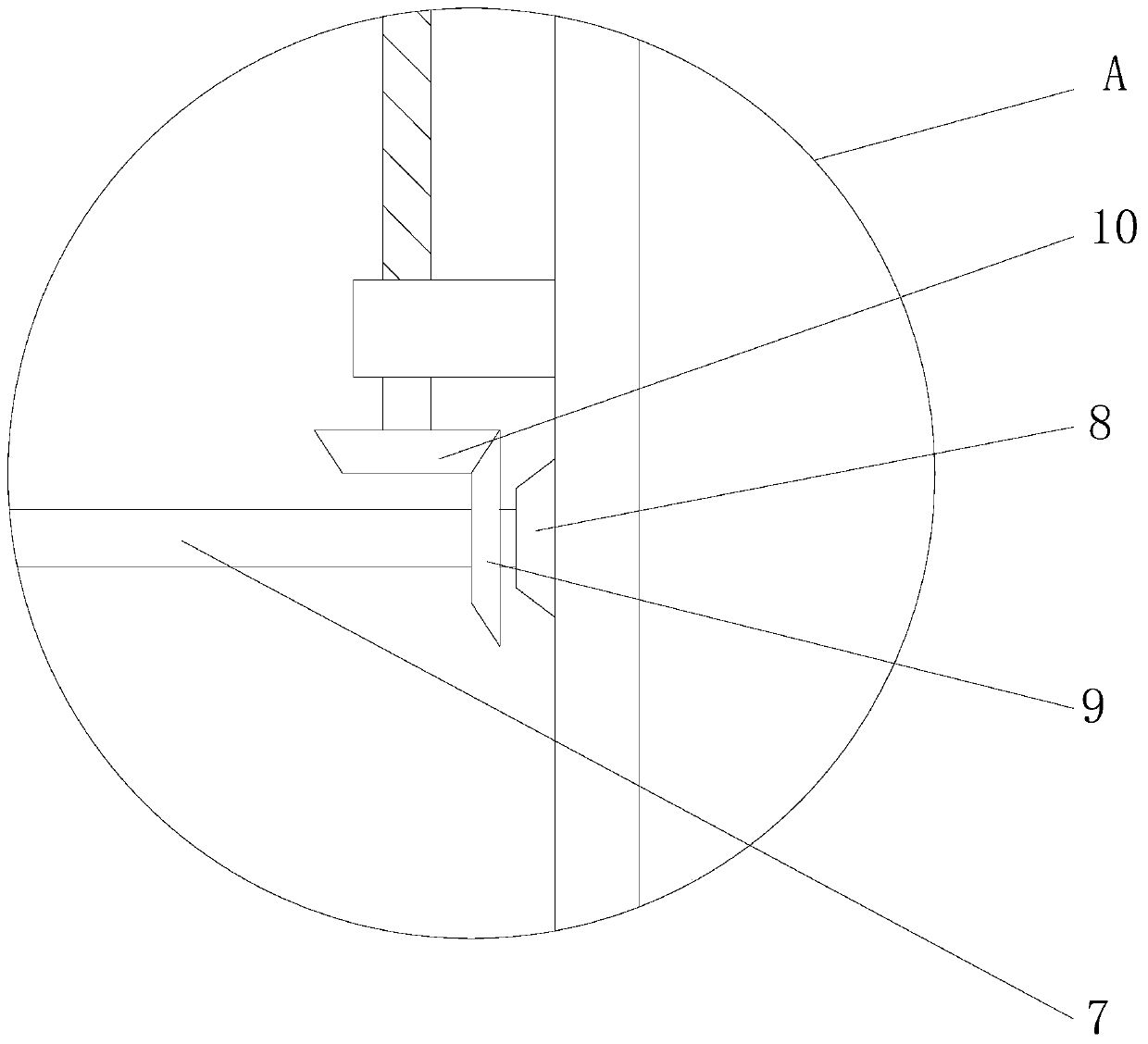
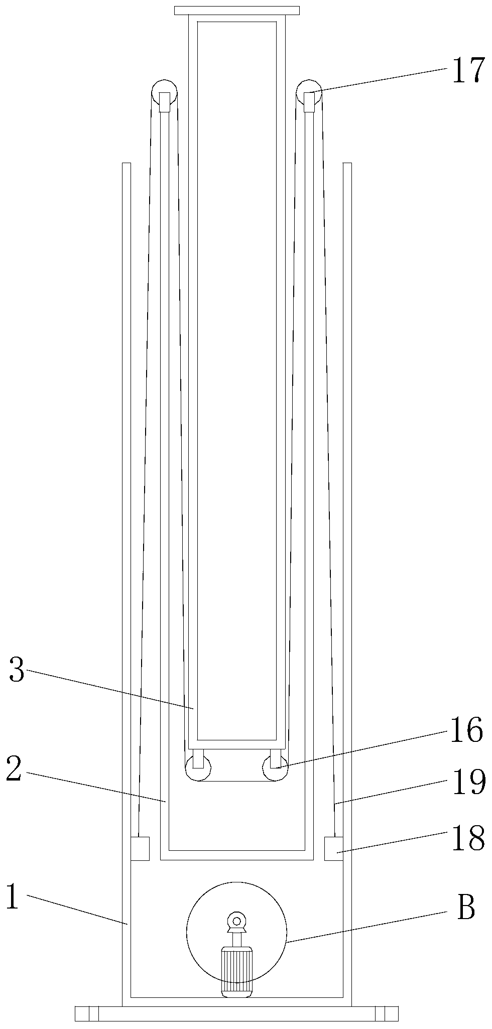
[0028] Such as Figure 1-5 As shown, the present invention provides a technical solution: a telescopic CT measuring rod, including an outer rod body 1, a middle rod body 2 and an inner rod body 3, a motor 4 is fixed on the inner bottom surface of the outer rod body 1, and the motor 4 is set as a forward and reverse motor , the end of the output shaft of the motor 4 is fixed with a bevel gear 1, the bevel gear 5 is meshed with the bevel gear 2 6, the bevel gear...


PUM


Abstract

The invention discloses a retractable CT (Computerized Tomography) measuring rod and a measuring method thereof. The measuring rod comprises an outer rod body, a middle rod body and an inner rod body;a motor is fixed on a bottom surface at the interior of the outer rod body; a bevel gear I is fixed on an end part of an output shaft of the motor; the bevel gear I is meshed with a bevel gear II; the bevel gear II is fixedly sleeved on a middle end of a rotating shaft; both ends of the rotating shaft are rotatably connected with a bearing seat I; the bearing seat I is fixed on an inner wall of the outer rod body; a bevel gear III is fixed on an end part of the rotating shaft; the bevel gear III is meshed with a bevel gear IV; the bevel gear IV is fixedly sleeved on a bottom end of a lead screw; two ends of the lead screw are respectively and rotatably disposed on a bearing seat II; and the bearing seat II is further fixed on the inner wall of the outer rod body. According to the retractable CT (Computerized Tomography) measuring rod and the measuring method thereof disclosed by the invention, by disposing the lead screw, a lead screw sleeve, a guide rail, a roller, a pulley I, a pulley II, a pothook and a steel wire rope, the problems that the rods are easy to incline and low in retraction efficiency when the conventional CT measuring rods are spliced are solved.

Description

technical field [0001] The invention relates to the technical field of electric wire measurement, in particular to a telescopic CT measuring rod and a measuring method thereof. Background technique [0002] When carrying out a current flow in the substation, the ordinary measuring pole needs to be spliced ​​by multiple insulating rods, and the primary line of the current flow is hung to the busbar side and the line side of the current transformer in the power failure interval. Due to the high voltage level of 220kV to the ground Due to the long distance, the weight of the rod itself will inevitably tilt during the hooking process, and there is a risk of accidentally touching the adjacent live space, and the splicing efficiency is low, and the entire measuring rod is inconvenient to retract. Therefore, the present invention designs a telescopic CT measuring rod and Its measurement method to solve the above problems. Contents of the invention [0003] (1) Solved technical p...

Claims


Application Information

Patent Timeline
Patent Type & Authority Applications(China)
IPC IPC(8): G01R1/02G01R31/00
CPCG01R1/02G01R31/00
Inventor 崔宇阳王佳伟王兴涛孔龙马康董迎朝卫巍王莉琳钱学鹏杨俊王瀚
Owner KUYTUN POWER SUPPLYING CO STATE GRID XINJIANG ELECTRIC POWER CO
Learn More