
Coated fiber reflection mirror fixing method

A technology of coated optical fiber and fixing method, which is applied to the coupling of optical waveguides and the transmission of sensing components by optical devices, etc., can solve the problems affecting the measurement results and service life of reflective optical fiber sensors, and achieve the goal of ensuring measurement results and service life Effect

Active Publication Date: 2019-11-12
SHANGHAI RUNJING ENERGY TECH
View PDF3 Cites 1 Cited by
  • Summary
  • Abstract
  • Description
  • Claims
  • Application Information

AI Technical Summary

Problems solved by technology

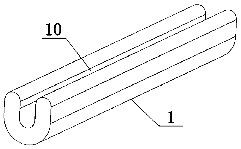
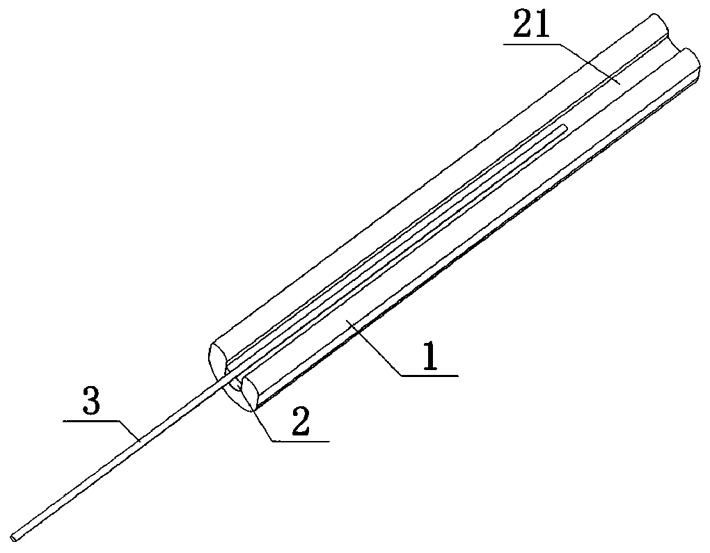
[0004] In the existing packaging structure, when the coated optical fiber is fixed, the coated optical fiber is usually packaged in a quartz glass tube, and in order to ensure the reliability of the fixation, the length of the gel packaging must be greater than 25mm, because the packaging gel is sealed in the quartz glass tube Therefore, the thermal expansion and contraction of the gel will cause it to flow along the length of the quartz glass tube, thereby generating axial and radial stress on the coated optical fiber, affecting the measurement results and service life of the reflective optical fiber sensor

Method used


Image

  • Coated fiber reflection mirror fixing method
  • Coated fiber reflection mirror fixing method
  • Coated fiber reflection mirror fixing method

Examples


Embodiment Construction

[0033] Embodiments of the present invention will be described in detail below, and examples of the embodiments are shown in the drawings, wherein the same or similar reference numerals denote the same or similar components or components having the same or similar functions throughout. The embodiments described below by referring to the figures are exemplary and are intended to explain the present invention and should not be construed as limiting the present invention.

[0034] In the description of the present invention, unless otherwise clearly stipulated and limited, the terms "connected", "connected" and "fixed" should be understood in a broad sense, for example, it can be a fixed connection, a detachable connection, or a mechanical connection. A connection can also be an electrical connection, a direct connection, or an indirect connection through an intermediary, or an internal connection between two elements or an interaction relationship between two elements. Those of o...


PUM


Abstract

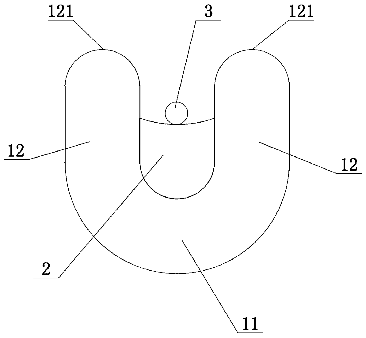
The invention belongs to the technical field of reflection mirror packaging and discloses a coated fiber reflection mirror fixing method. The method comprises the steps of setting a quartz packaging element with a through groove, and enabling a groove opening of the through groove to be upward; injecting gel into the through groove to form a first gel layer, wherein an outer side face of the firstgel layer facing the groove opening of the through groove is a supporting plane, so the supporting plane and the groove opening of the through groove are spaced; extending one end of a coated fiber into the through groove, enabling a part of the coated fiber extending into the through groove to extend along a through direction of the through groove, and setting up the coated fiber on the supporting plane; and injecting the gel into the through groove to form a second gel layer, thereby packaging the coated fiber into the through groove by the second gel layer. According to the method, deformation generated by the quartz packaging element when packaging gel carries out thermal expansion and contraction can be released through utilization of an unilateral opening of a through groove.

Description

technical field [0001] The invention relates to the technical field of reflector packaging, in particular to a method for fixing a coated optical fiber reflector. Background technique [0002] Reflective fiber optic sensors have the characteristics of excellent electrical insulation performance, radiation resistance, frequency response and safety. The reflector is a core optical device that makes up this kind of sensor, and its performance directly affects the normal operation and application of the sensor. Existing reflective optical fiber sensors usually use coated optical fiber, that is, coating at the output end of the optical fiber. In this kind of reflector, the coating structure is easily affected by the humid and hot environment, resulting in changes in reflectivity and affecting the performance of the reflector. It needs to be packaged to ensure its performance and strength. [0003] In order to ensure the performance and strength of the mirror, its packaging stru...

Claims


Application Information

Patent Timeline
Patent Type & Authority Applications(China)
IPC IPC(8): G02B6/36G01D5/353
CPCG01D5/353G02B6/36
Inventor 赵晓
Owner SHANGHAI RUNJING ENERGY TECH
Learn More