
Debris flow control parameter design optimization method considering freeze-thaw cycle effect

A freeze-thaw cycle and debris flow technology, applied in computing, electrical digital data processing, special data processing applications, etc., can solve problems such as not considering freeze-thaw cycles and high parameter values, achieving significant applicability advantages and strengthening pertinence , the effect of improving the accuracy of the value

Active Publication Date: 2019-11-12
INST OF EXPLORATION TECH OF CHINESE ACAD OF GEOLOGICAL SCI +1
View PDF3 Cites 11 Cited by
  • Summary
  • Abstract
  • Description
  • Claims
  • Application Information

AI Technical Summary

Problems solved by technology

[0006] The purpose of the present invention is to solve the above-mentioned defects in the prior art, and provide a design optimization method for debris flow prevention and control parameters considering the freeze-thaw cycle effect, aiming at solving the problem that the existing debris flow prevention and control engineering design parameters continue to use rock and soil in non-freeze-thaw areas Conventional physical parameters do not consider the effect of freeze-thaw cycles on the degradation of rock and soil properties, and there is a risk of high parameter values

Method used


Image

  • Debris flow control parameter design optimization method considering freeze-thaw cycle effect
  • Debris flow control parameter design optimization method considering freeze-thaw cycle effect
  • Debris flow control parameter design optimization method considering freeze-thaw cycle effect

Examples


Embodiment

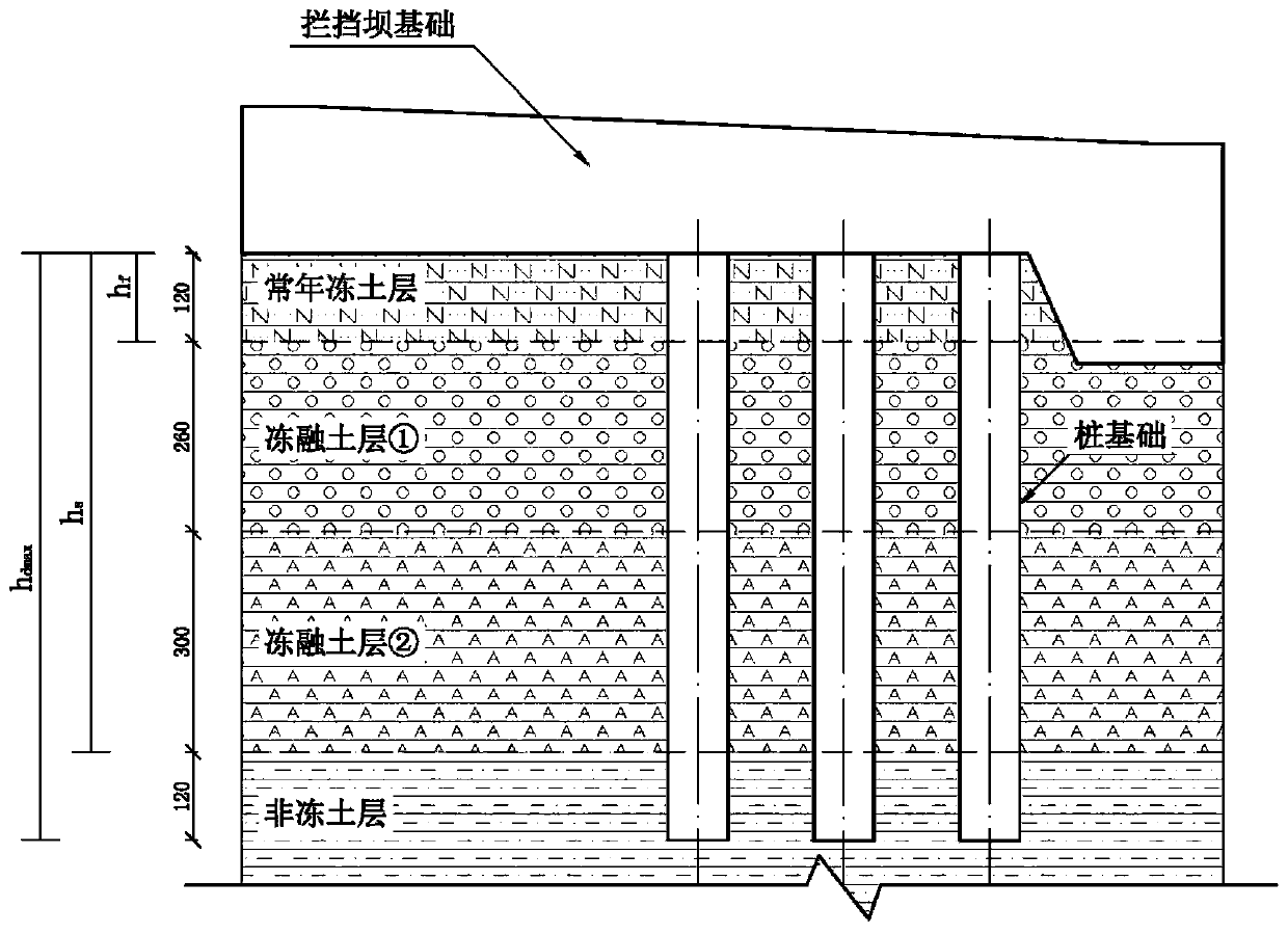
[0059] Such as figure 2 As shown, a debris flow ditch is located in Jiangda County, Gongbu, Tibet. According to the survey data, the permafrost depth of the area where the debris flow ditch is located is h f = 1.2m, depth of seasonal frozen soil h s = 6.8m, a sand control dam is planned to be laid, and the foundation soil layer at the dam foundation is exposed in total 4 layers, and their friction coefficients are: f of the permafrost layer f =0.40; f of seasonal frozen soil layer ① 1 =0.45 (thickness h 1 =2.6m), f of seasonal frozen soil layer ② 2 =0.50 (thickness h 2 =3.0m); f of the underlying non-frozen soil layer 0 = 0.60.

[0060] According to the fortification level and specific prevention and control objectives of the prevention and control project, the design service life of the project is determined to be 20 years, the dam foundation structure adopts pile foundation, and the maximum design depth of the base is h dmax = 8.0 m. According to the movement parame...


PUM


Abstract

The invention provides a debris flow control parameter design optimization method considering a freeze-thaw cycle effect. The debris flow control parameter design optimization method comprises: firstly, obtaining original friction coefficients and thicknesses of perennial frozen soil, seasonal frozen soil and deep non-frozen soil of an engineering area according to exploration data; then, according to a reduction rate formula obtained through a large number of experiments and data statistics in the early stage, performing friction coefficient reduction of a freeze-thaw soil layer in combination with the designed service life (namely the freeze-thaw cycle index) and the seasonal frozen soil thickness; according to the relative relation between the maximum design depth of the foundation of the prevention and treatment project and the depth of the frozen soil layer, checking the anti-sliding stability of the structure according to the three conditions, finally comparing the anti-sliding stability coefficient with the required sliding safety coefficient, and designing the next step according to the result. According to the method, the problem that the base friction coefficient and theanti-sliding coefficient are lower than the design value due to the fact that the freezing and thawing cycle influence is not considered is solved, the pertinence and accuracy of engineering design parameter values can be enhanced, and deformation damage of the sand blocking dam under the frost heaving and thawing settlement conditions is prevented and relieved.

Description

technical field [0001] The invention belongs to the technical field of geotechnical engineering, and in particular relates to a method for designing and optimizing debris flow prevention and control parameters in consideration of freeze-thaw cycle effects. Background technique [0002] During the freezing-thawing cycle of rock and soil in high-cold and high-altitude areas, the soil structure is affected by cold generation, which can lead to changes in the engineering properties of the soil. When carrying out engineering activities such as roadbed construction, slope reinforcement, and geological disaster control in permafrost areas, because the newly exposed soil is subject to freeze-thaw weathering, in the relevant deformation and stability analysis, soil properties must be considered when selecting soil parameters. Changes in the nature of physical engineering. [0003] In the existing technology and research in the field of mechanical properties of frozen soil, most of t...

Claims


Application Information

Patent Timeline
Patent Type & Authority Applications(China)
IPC IPC(8): G06F17/50
Inventor 杨东旭游勇陈晓清刘建康熊德清黄海孙昊刘洋
Owner INST OF EXPLORATION TECH OF CHINESE ACAD OF GEOLOGICAL SCI
Learn More