
Inner shell heat dissipation air outlet system of air fryer

A technology of air fryer and wind system, which is applied to kitchen utensils, household utensils, roasters/barbecue grills, etc., which can solve the problems of poor heat dissipation and air flow of air fryers, and achieve simple structure and high efficiency. The effect of wind cooling

Pending Publication Date: 2019-11-15
宁波爱科特厨电科技有限公司
View PDF0 Cites 0 Cited by
  • Summary
  • Abstract
  • Description
  • Claims
  • Application Information

AI Technical Summary

Problems solved by technology

[0003] Existing air fryers generally include an outer shell and an inner shell arranged in the outer shell. The outer shell and the inner shell cooperate to form an air flow space. The inner shell includes an upper inner shell and a lower inner shell. Cover, the reflector cooperates with the upper inner shell to form a heat dissipation cavity, and a centrifugal fan is installed in the heat dissipation cavity, and the heat in the heat dissipation cavity is blown into the air flow space through the centrifugal fan blowing to the surroundings, and finally discharged from the air outlet at the bottom of the shell. However, because there are no constraints around the fan, the airflow above the reflector is not guided, resulting in unsmooth airflow in the air fryer cavity, poor heat dissipation, and room for improvement

Method used


Image

  • Inner shell heat dissipation air outlet system of air fryer
  • Inner shell heat dissipation air outlet system of air fryer
  • Inner shell heat dissipation air outlet system of air fryer

Examples


Embodiment Construction

[0015] A specific embodiment of the present invention will be described in detail below in conjunction with the accompanying drawings, but it should be understood that the protection scope of the present invention is not limited by the specific embodiment.

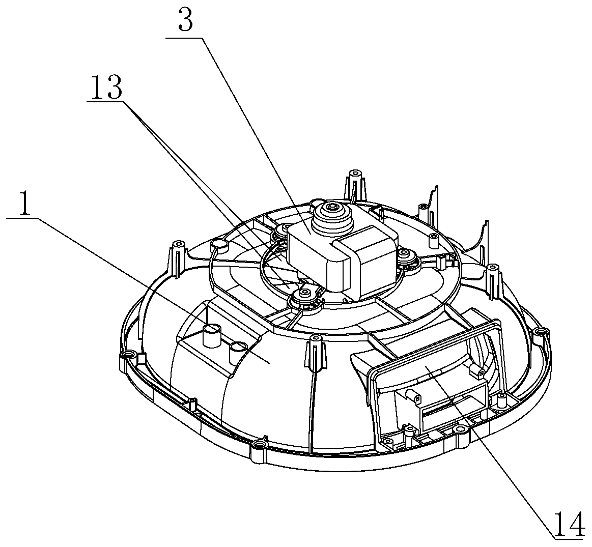
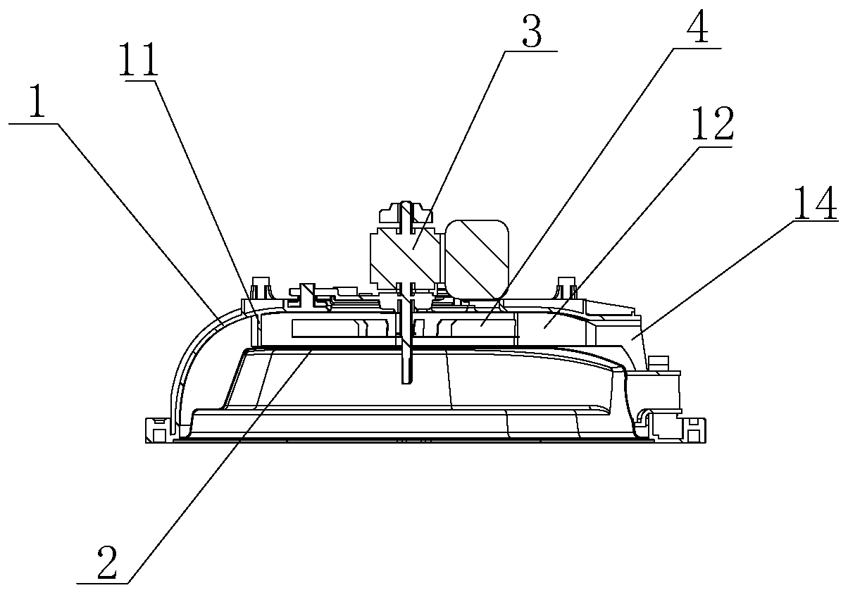
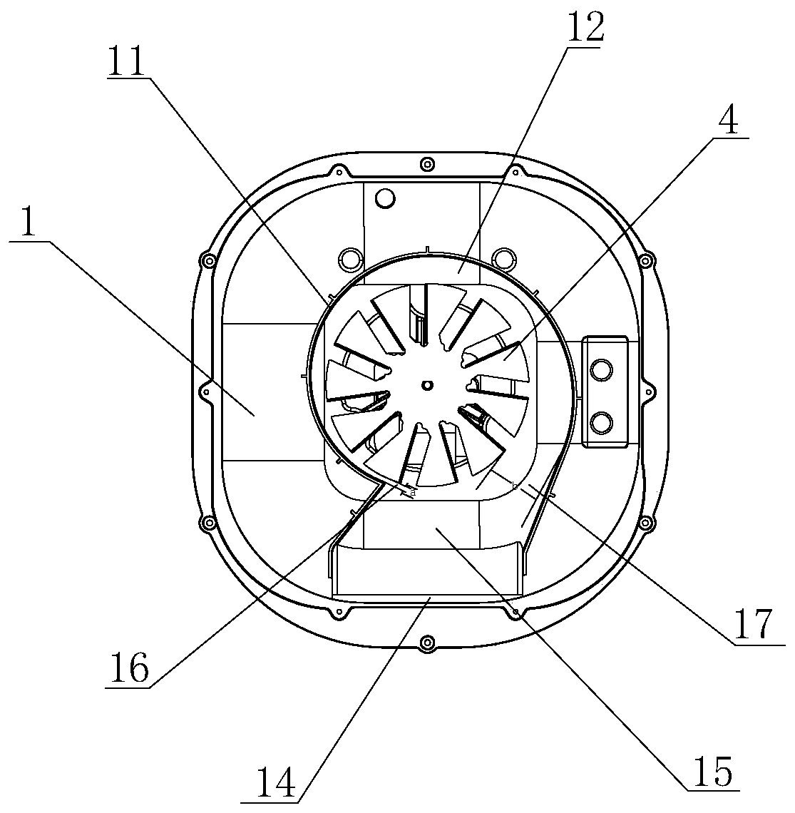
[0016] The heat dissipation and air outlet system of the inner shell of the air fryer of the present invention is as follows: figure 1 and figure 2 As shown, it includes an upper inner shell 1, a reflector 2, a motor 3 and a fan blade 4. The upper inner shell 1 is a cover structure with the opening facing downward. The reflector 2 is arranged in the upper inner shell 1, and the Cooperate to form a circulating cooling cavity 12, the motor 3 is installed on the top wall of the upper inner shell 1 and the drive shaft of the motor 3 extends into the circulating cooling cavity 12 and is connected with the fan blade 4 in it to drive the fan blade 4 to rotate, Preferably, a through hole is opened on the top of the upper inner s...


PUM


Abstract

The invention discloses an inner shell heat dissipation air outlet system of an air fryer. The inner shell heat dissipation air outlet system comprises an upper inner shell, a reflection cover, a motor and fan blades, the reflection cover is disposed in the upper inner shell, coaming plates are disposed on the reflection cover and / or the upper inner shell to form a circulating heat dissipation cavity therebetween, and an air outlet is formed in a peripheral wall of the upper inner shell; the motor is connected with the fan blades in the circulating heat dissipation cavity, and an air inlet isformed in a top wall of the upper inner shell; and the circulating heat dissipation cavity has a communication portion, the coaming plates on two sides of the communication portion are in clearance fit with outer edges of the fan blades to respectively form an air inlet gap and an air outlet gap, and the spacing of the air inlet gap is less than that of the air outlet gap. According to the inner shell heat dissipation air outlet system disclosed by the invention, the circulating heat dissipation cavity is formed between the upper inner shell and the reflection cover through the coaming platesto restrain the air from entering from the air inlet and discharging from the air outlet, and meanwhile, by controlling the air inlet gap to be less than the air outlet gap, the air can be prevented or reduced from entering the circulating heat dissipation cavity again through the air inlet gap, thereby achieving the purpose of efficient air-out heat dissipation.

Description

technical field [0001] The invention relates to the technical field of kitchen appliances, in particular to a heat dissipation and air outlet system for an inner shell of an air fryer. Background technique [0002] The air fryer can make delicious French fries with up to 80% less fat than traditional electric fryers by using high-speed air circulation technology. Food snacks, seafood dishes, etc.; moreover, because the air fryer only uses air to fry, it produces less odor and steam than traditional frying, so it is easier to clean, safer and more economical. [0003] Existing air fryers generally include an outer shell and an inner shell arranged in the outer shell. The outer shell and the inner shell cooperate to form an air flow space. The inner shell includes an upper inner shell and a lower inner shell. Cover, the reflector cooperates with the upper inner shell to form a heat dissipation cavity, and a centrifugal fan is installed in the heat dissipation cavity, and the ...

Claims


Application Information

Patent Timeline
Patent Type & Authority Applications(China)
IPC IPC(8): A47J37/06
CPCA47J37/0641
Inventor 姚进根
Owner 宁波爱科特厨电科技有限公司
Learn More