Welding slag fire welding and annealing device, permanent magnet gap determination method and slag removing tool

An annealing device and permanent magnet technology, applied in the field of slag cleaning tools and welding slag fire annealing devices, can solve problems such as hidden dangers of personal injury, hidden dangers of fire, difficult cleaning of fusion, splashing, etc.

Pending Publication Date: 2019-11-15
CHINA CONSTR FIFTH ENG DIV CORP LTD
View PDF0 Cites 0 Cited by
  • Summary
  • Abstract
  • Description
  • Claims
  • Application Information

AI Technical Summary

Problems solved by technology

[0002] Metal welding is often used in on-site operations such as civil engineering. For example, on-site welding is inevitable in steel structure construction operations. The iron-containing welding slag metal solution dropped at 100°C is very likely to become a major safety hazard for construction personnel and a fire hazard.
At present, there is no corresponding welding slag annealing device. The metal disc is usually placed under the welding position to receive the welding slag. When the welding slag falls on the metal disc, there is still the problem of splashing, and the metal disc There is a certain fusion between the upper cooling and the metal disc, which is difficult to clean

Method used


Image

  • Welding slag fire welding and annealing device, permanent magnet gap determination method and slag removing tool
  • Welding slag fire welding and annealing device, permanent magnet gap determination method and slag removing tool
  • Welding slag fire welding and annealing device, permanent magnet gap determination method and slag removing tool

Examples


Embodiment Construction

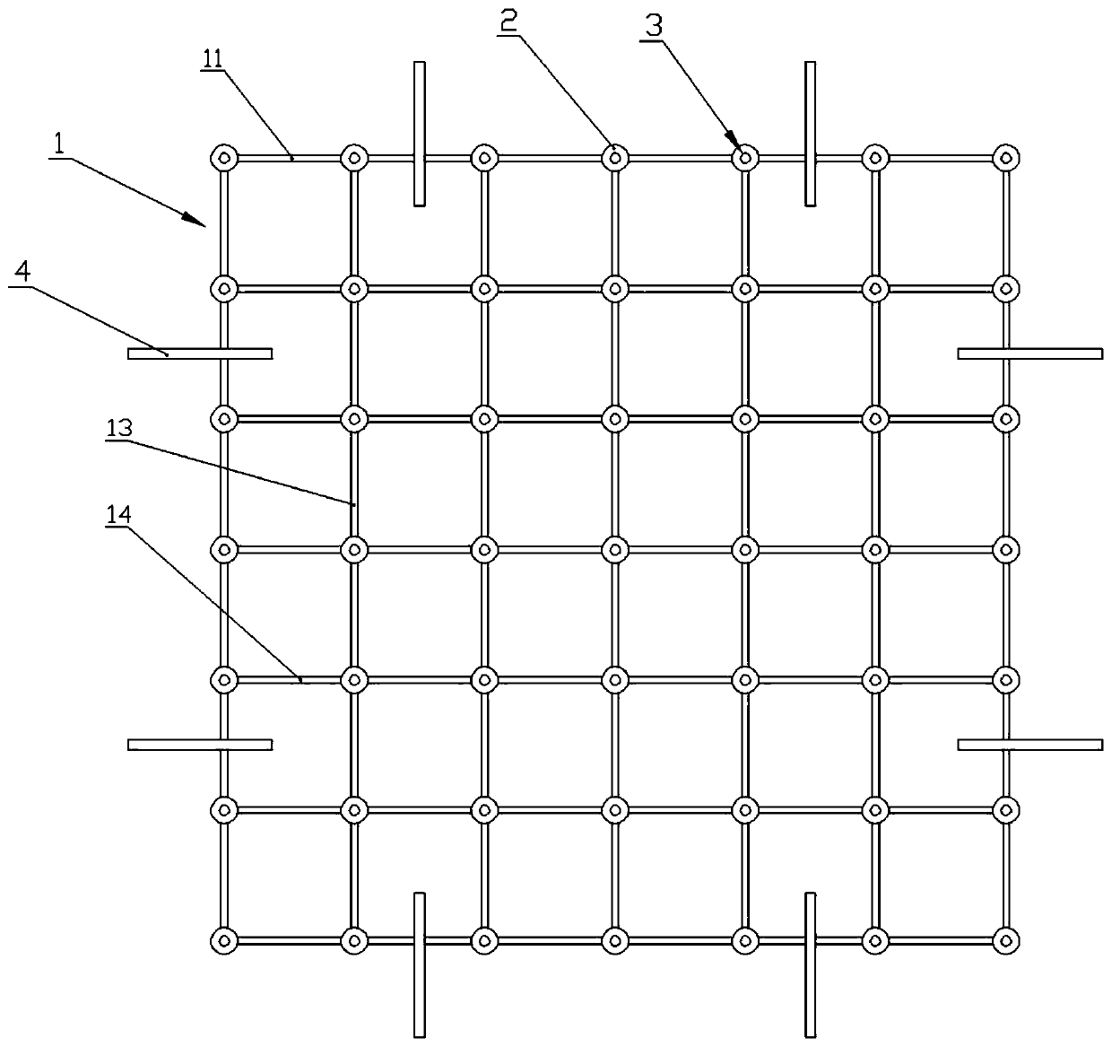
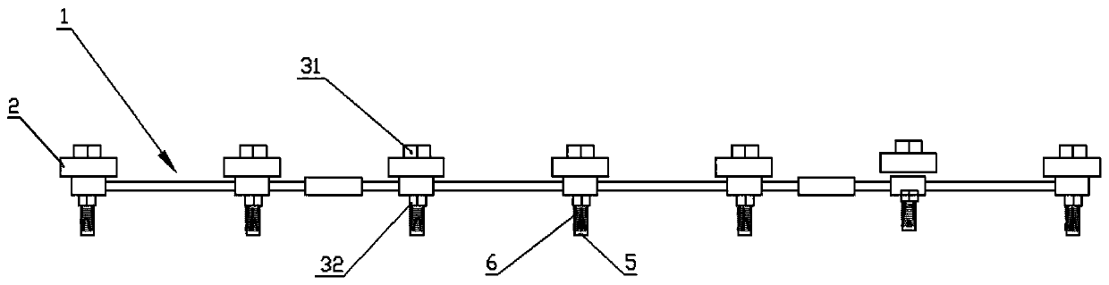
[0061] Such as figure 1 As shown, the welding slag annealing device disclosed in this embodiment includes a magnetic attraction grid 1 , a permanent magnet 2 , a locking assembly 3 and a hook 4 .

[0062] The magnetic suction grid 1 is a mesh grid made of insulating and high-temperature resistant industrial plastics, including a frame 11, a positioning seat 12, a vertical grid bar 13 and a horizontal grid bar 14; the frame is a rectangular frame; the positioning seat 12 is a circle Cylindrical seat body, there are three types of positioning seats with different heights, one is high magnetic point positioning seat A, one is medium magnetic point positioning seat B, and the other is low magnetic point positioning seat C; The grid bars 13 and the horizontal grid bars 14 are arranged in a staggered manner in the frame, and the inner area of ​​the frame is composed of multiple unit modules; The high magnetic point positioning seat A and the low magnetic point positioning seat C ar...


PUM

PropertyMeasurementUnit
thicknessaaaaaaaaaa
diameteraaaaaaaaaa

Abstract

The invention discloses a welding slag fire welding and annealing device, a permanent magnet gap determination method and a slag removing tool. The device comprises a magnetic sucking grid, permanentmagnets and a locking module; the magnetic sucking grid comprises multiple positioning bases with different heights; two adjacent positioning bases are connected through grid strips; and the permanentmagnets are positioned on the corresponding positioning bases and locked through locking modules. The arrangement gaps of the permanent magnets are firstly calculated and determined; then, the magnetic sucking grid comprising the positioning bases is manufactured; the gaps of the positioning bases are equal to the gaps of the permanent magnets; the permanent magnets are assembled on the corresponding positioning bases through the locking modules for use; the device is mounted under the welding operation in use for absorption cooling of welding slag high-temperature molten metal in an effective fire welding range, so that potential safety hazards caused by direct falling of welding slag in the welding operation are prevented, and the major personal injury and the fire risk are eliminated;and the permanent magnets are temporarily demagnetized after welding for slag removal, so that the welding slag is conveniently cleaned and collected.

Description

technical field [0001] The invention belongs to the technical field of on-site construction safety of steel structures, and in particular relates to a welding slag annealing device, a method for determining the distance between permanent magnets and a slag removal tool. Background technique [0002] Metal welding is often used in on-site operations such as civil engineering. For example, on-site welding is inevitable in steel structure construction operations. The iron-containing welding slag metal solution dropped at 100°C is very likely to become a major safety hazard for construction personnel and a fire hazard. At present, there is no corresponding welding slag annealing device. The metal disc is usually placed under the welding position to receive the welding slag. When the welding slag falls on the metal disc, there is still the problem of splashing, and the metal disc There is a certain fusion between the upper cooling and the metal disc, which is difficult to clean....

Claims


Application Information

Patent Timeline
Patent Type & Authority Applications(China)
IPC IPC(8): B23K37/00
CPCB23K37/00
Inventor 唐志超孔阳陈阳周灵次裴汉江
Owner CHINA CONSTR FIFTH ENG DIV CORP LTD
Why Eureka
Try Eureka