Circulating conveying structure

A circulating conveying and chain technology, applied in conveyors, transportation and packaging, etc., can solve the problems of short conveying stroke and insufficient conveying power of thick chains, and achieve the effect of continuous and stable chain operation, avoiding direct contact and improving utilization rate.

Pending Publication Date: 2019-11-15
HUAXIAO PRECISION SUZHOU
View PDF0 Cites 4 Cited by
  • Summary
  • Abstract
  • Description
  • Claims
  • Application Information

AI Technical Summary

Problems solved by technology

[0004] Therefore, the technical problem to be solved by the present invention is that the existing conveying structure needs to overcome the defects of short conveying stroke and insufficient conveying power due to the need to overcome the self-weight of the thick chain

Method used


Image

  • Circulating conveying structure
  • Circulating conveying structure
  • Circulating conveying structure

Examples


Embodiment 1

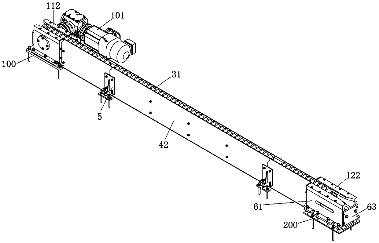
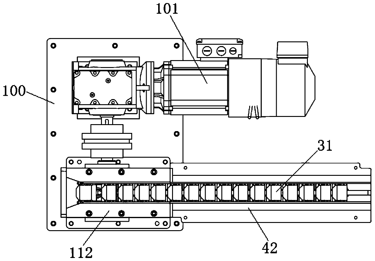
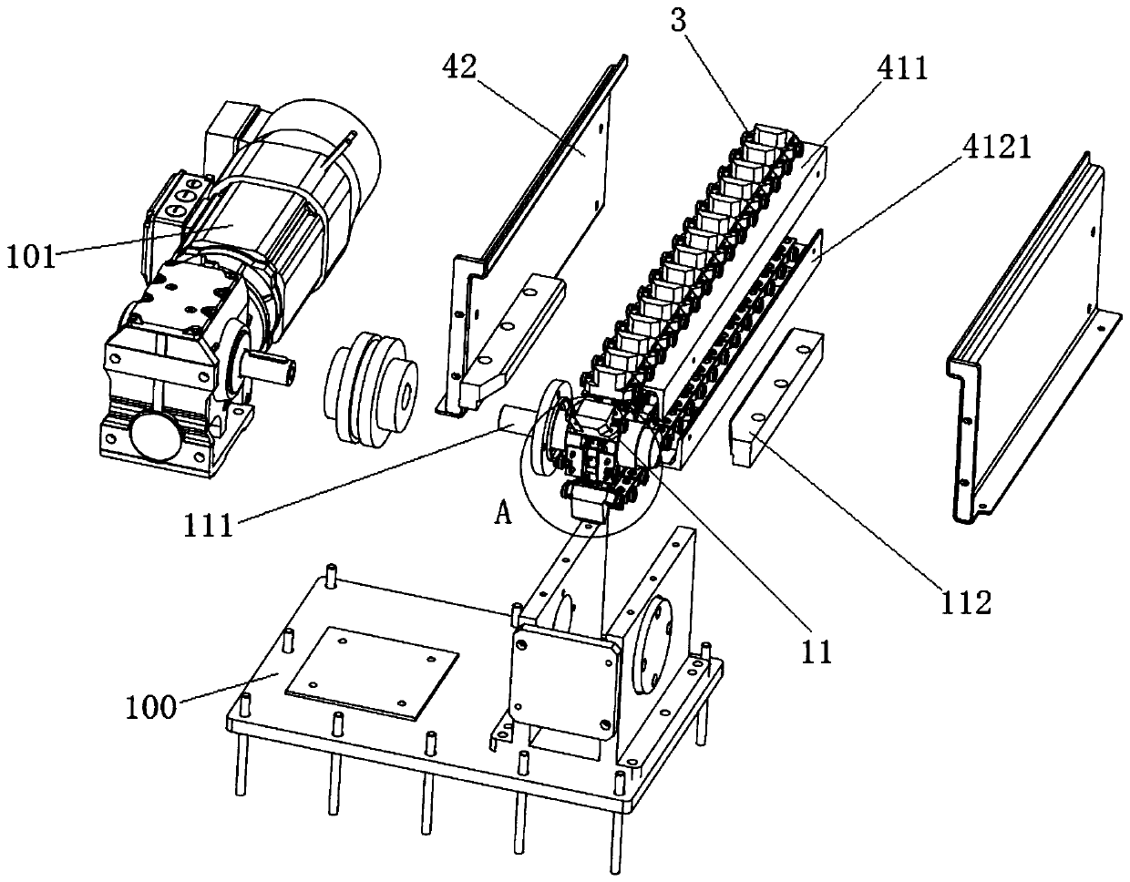
[0063] This embodiment provides a circular conveying structure, such as figure 1 As shown, it includes a sprocket, a chain 2 , several carrying components 3 and a support component 4 , the sprocket includes a driving wheel 11 and a driven wheel 12 , and the chain 2 is tightly wound around the driving wheel 11 and the driven wheel 12 . Such as figure 2 and image 3 As shown, the driver 101 is installed on the first mounting base 100, the drive shaft of the driver 101 is connected with the driving shaft 111 of the driving wheel 11, the driver 101 is suitable for driving the driving wheel 11 to rotate around the axis, and the second wheel located on both sides of the driving wheel 11 A mounting base 100 is vertically provided with fixing plates, and the driving shaft 111 is passed through and rotated on the fixing plates on both sides to realize the positioning of the driving wheel 11. In this embodiment, the driver 101 adopts a motor.

[0064] Such as Figure 5 and Figure ...


PUM


Abstract

The invention provides a circulating conveying structure. The circulating conveying structure comprises a chain wheel, a chain, a plurality of carrying components and a supporting component. The carrying components are arranged on a chain link of the chain. A guiding support part, of the supporting component, under the chain plays the role of guiding support for the loading components, so as to avoid the falling of the middle part when the chain is too long or too heavy. A driver does not need to overcome the self-weight of the chain, and can fully use the driving force to drive the chain to rotate and transport, and the chain operation is stable. The chain is provided with multi-stage supporting components; side guarding plates are arranged on both sides of the chain and are detachably connected together through the supporting components; at the same time, according to the characteristics of the chain itself, the chain links can be extended or shortened by docking so that the circulating conveying structure can realize the overall extension or shortening according to the distance of the transport, and the design section by section is convenient for maintenance.

Description

technical field [0001] The invention belongs to the technical field of transportation equipment, and in particular relates to a circular conveying structure. Background technique [0002] With the rise of China's manufacturing technology, the production efficiency of enterprises has developed rapidly, and the production lines of enterprises have also quietly transitioned from fixed lines that can only produce one product to flexible production lines with strong adaptability. In the assembly line, the transportation of material transport vehicles is a very important link. The weight of material transport vehicles increases after carrying materials, and the efficiency of manual push is low. The process of material transport vehicles from loading materials off-line to on-line feeding is relatively slow. [0003] In the prior art, in order to improve the transport efficiency of the material transport vehicle, the chain is used to directly pull and drag the material transport veh...

Claims


Application Information

Patent Timeline
Patent Type & Authority Applications(China)
IPC IPC(8): B65G17/12B65G17/42B65G23/44
CPCB65G17/12B65G17/42B65G23/44
Inventor 傅海龙姜海波许建逸
Owner HUAXIAO PRECISION SUZHOU
Why Eureka
Try Eureka