
General rail shifting device for petroleum drilling machine
A transfer device and track-type technology, which is applied in the direction of transportation and packaging, conveyors, mechanical conveyors, etc., can solve the problems that different track-type transfer devices cannot be used universally, and achieve universality, optimization of limit devices, limit bit device for simple effects
- Summary
- Abstract
- Description
- Claims
- Application Information
AI Technical Summary
Problems solved by technology
Method used
Image

Examples
Embodiment Construction
[0027] The specific implementation manner of the present invention will be further described below in conjunction with the accompanying drawings.
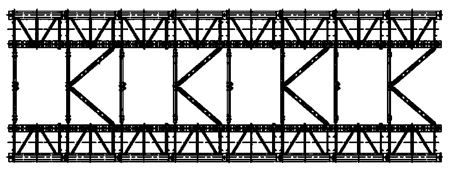
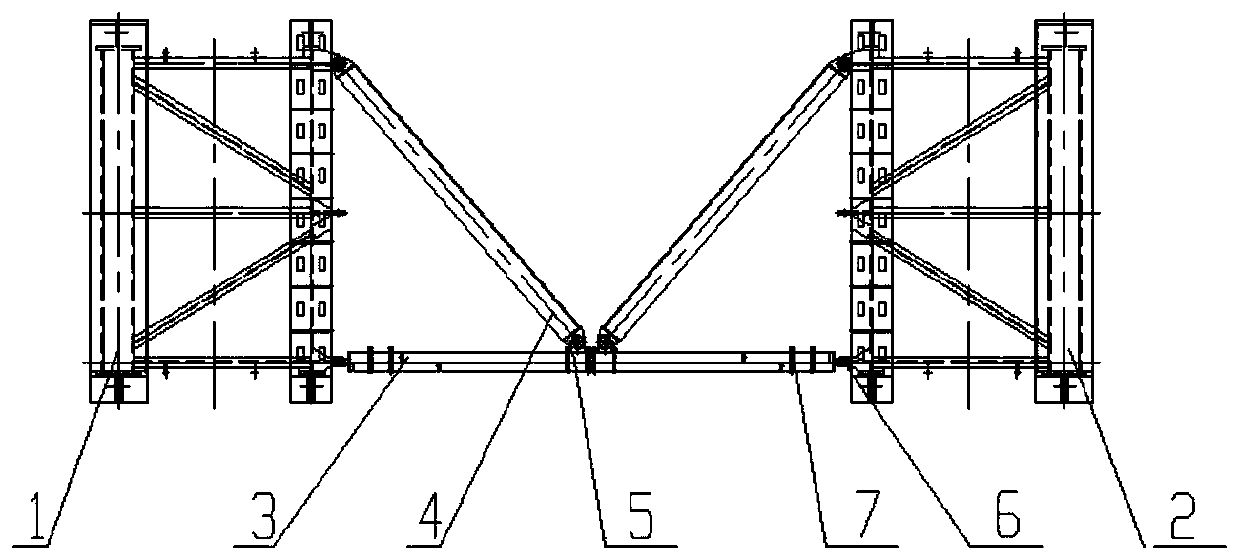
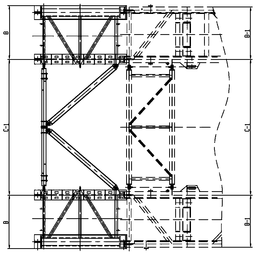
[0028] Such as Figure 1-8 As shown, the universal rail-type transfer device for oil drilling rigs of the present invention is characterized in that it includes a group of transfer units sequentially connected by connecting pins 6, and each transfer unit includes a film rack I1 and a film rack arranged on both sides. II2, connecting the combined beam 3 and inclined beam 4 of the two sides of the film rack I1 and the film rack II2, the two ends of the combined beam 3 are respectively connected to the film rack I1 and the film rack II2 through the connecting pins 6 Connection, the combined beam 3 and the inclined beam 4 are connected through the ear seat 5 of the inclined beam.
[0029] The set of transfer units includes 6-10 transfer units.
[0030] The combined beam 3 includes a group of beams, and a beam card 7 connecting every ...
PUM
 Abstract
Description
Claims
Application Information