Big-diameter water supply and drainage pipeline inner wall desilting device
A dredging device and technology for water supply and drainage, applied in the field of water supply and drainage, can solve the problems of inability to achieve rapid desilting effect of water supply and drainage pipelines, cumbersome desilting operation of water supply and drainage pipelines, etc., and achieve sufficient cleaning effect, lifting speed, and dredging operation Efficient effect
- Summary
- Abstract
- Description
- Claims
- Application Information
AI Technical Summary
Problems solved by technology
Method used
Image
Examples
Embodiment 1
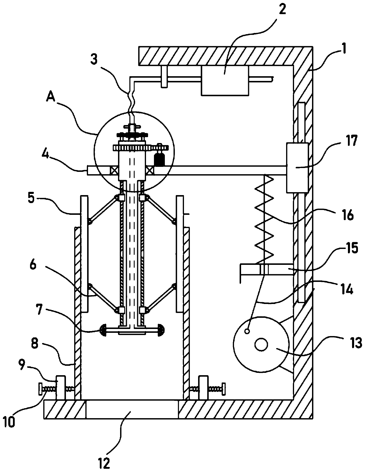
[0023] see Figure 1-4 , a dredging device for the inner wall of a large-diameter water supply and drainage pipeline, including a bracket 1, on which a sewage hole 12 corresponding to the pipeline 8 is arranged, and on the bracket 1, a horizontal plate 4 is driven and connected by a vertical reciprocating mechanism, and the horizontal plate 4 is provided with a rotating mechanism extending to the inside of the pipeline 8. The rotating mechanism is connected with a scraper 5 abutting against the inner wall of the pipeline 8 through an adjustment structure. The bottom of the rotating mechanism is provided with a nozzle 7 facing the inner wall of the pipeline 8. The nozzle 7 is connected to the outside Pressure water connection.
[0024] When the pipeline 8 is desilted, the pipeline 8 is vertically placed on the support 1, and the drain hole 12 on the support 1 corresponds to the inside of the pipeline 8, so that the sludge is discharged from the drain hole 12 conveniently.
[0...
Embodiment 2
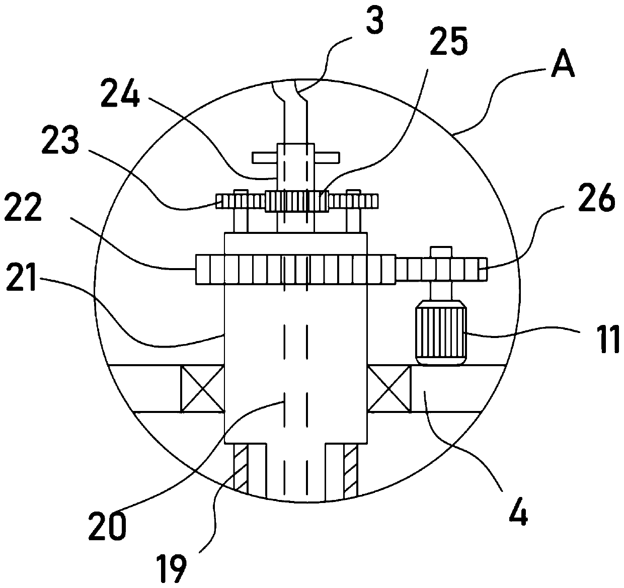
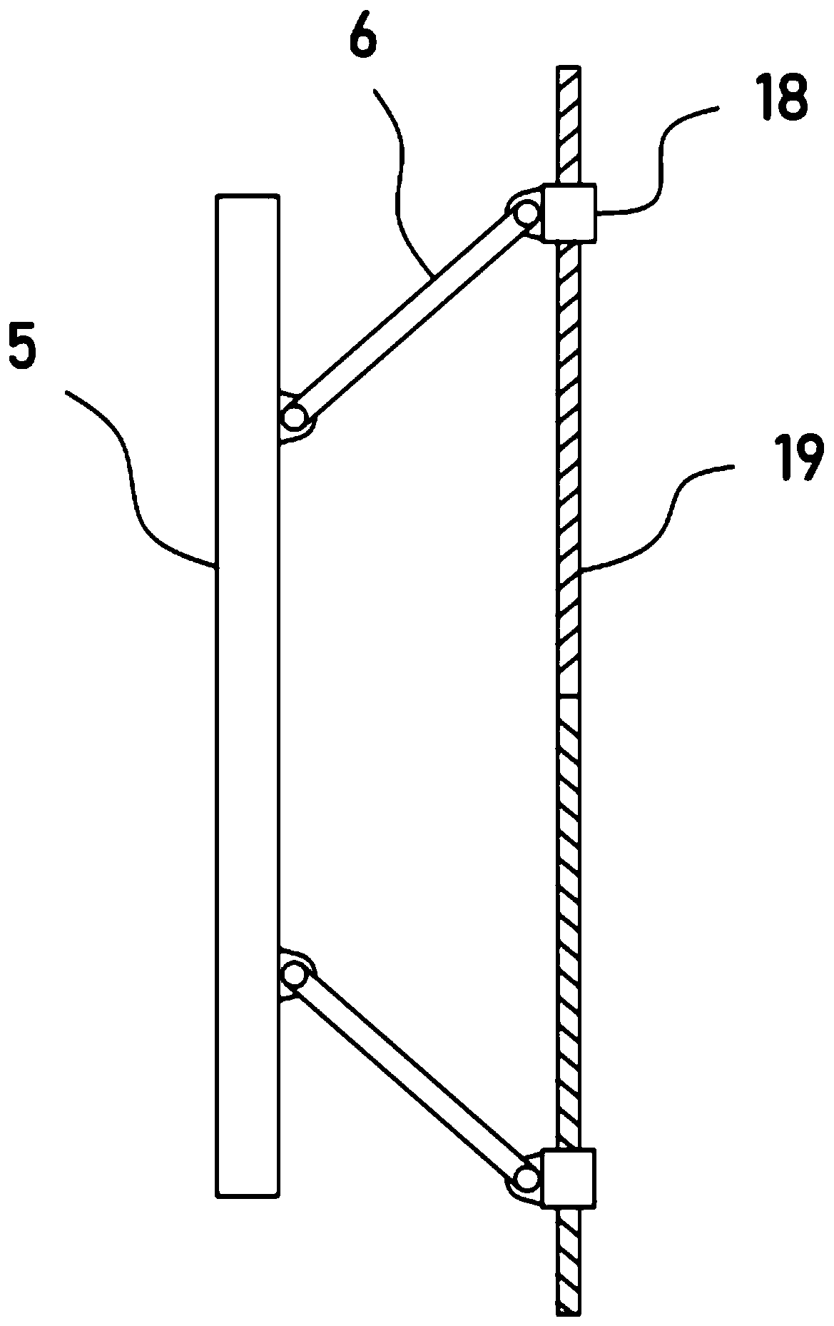
[0029] On the basis of Example 1, in order to improve the adaptability of the dredging device, that is, to be able to dredge water supply and drainage pipes with different inner diameters, the device is also provided with an adjustment structure, which specifically includes a rotating column embedded in the rotating column Two threaded rods 19 with opposite helical directions fixed coaxially on 21 are screwed with threaded sleeves 18 on the two threaded rods 19 , and a support rod 6 is hinged between the threaded sleeves 18 and the scraper 5 . A rotating shaft 24 is pivotally connected to the rotating column 21 , a main gear 25 is sheathed and fixed on the rotating shaft 24 , and an auxiliary gear 23 meshing with the main gear 25 is coaxially fixed on the threaded rod 19 .
[0030] The main gear 25 can be driven to rotate by rotating the rotating shaft 24, and the main gear 25 drives the threaded rod 19 to rotate through the secondary gear 23 meshed with it. , the threaded sle...
PUM
 Abstract
Description
Claims
Application Information
 - R&D
- Intellectual Property
- Life Sciences
- Materials
- Tech Scout
- Unparalleled Data Quality
- Higher Quality Content
- 60% Fewer Hallucinations
Browse by: Latest US Patents, China's latest patents, Technical Efficacy Thesaurus, Application Domain, Technology Topic, Popular Technical Reports.
© 2025 PatSnap. All rights reserved.Legal|Privacy policy|Modern Slavery Act Transparency Statement|Sitemap|About US| Contact US: help@patsnap.com


