Built-in limiting device for slewing bearing and capable of adjusting angle range and application of built-in limiting device

A technology of slewing bearings and limit devices, which is applied in transmissions, transmission parts, gear transmissions, etc., can solve the problems of cumbersome installation and lifespan that cannot meet the needs of equipment, and achieve simple and effective connection of parts, tightness of the whole, and convenient adjustment Effect

Active Publication Date: 2019-11-15
山东华岳新能源有限公司
View PDF8 Cites 0 Cited by
  • Summary
  • Abstract
  • Description
  • Claims
  • Application Information

AI Technical Summary

Problems solved by technology

However, the installation form of this kind of limit is too cumbersome, and the position of the limit and the stopper must be adjusted on site according to the installation factors of the project; and the limit is installe

Method used


Image

  • Built-in limiting device for slewing bearing and capable of adjusting angle range and application of built-in limiting device
  • Built-in limiting device for slewing bearing and capable of adjusting angle range and application of built-in limiting device
  • Built-in limiting device for slewing bearing and capable of adjusting angle range and application of built-in limiting device

Examples


Embodiment Construction

[0034] The present invention will be further described below in conjunction with the accompanying drawings and specific embodiments.

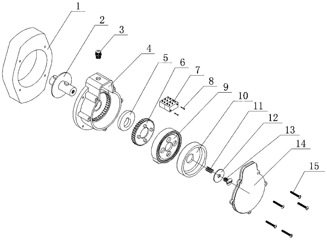
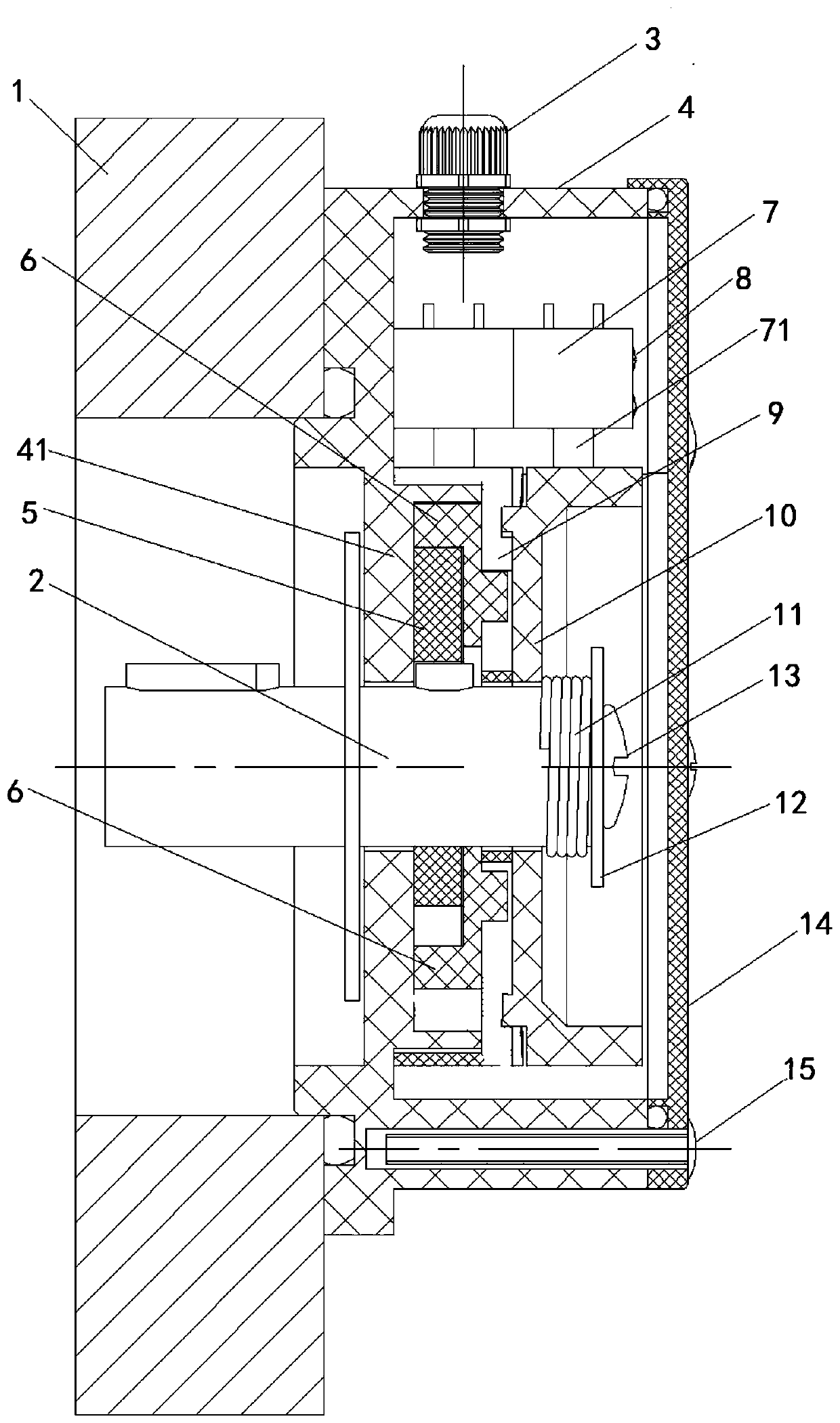
[0035] like Figure 2~3 As shown, an embodiment of the built-in limit device for the adjustable angle range of the slewing bearing designed by the present invention, the built-in limit device includes an input shaft core 2, an eccentric wheel 5, a toggle gear 6, and a limit switch 7 , the lower balance wheel 9 and the upper balance wheel 10, and are provided with a main housing 4, and the entire built-in limiter is fixed on the slewing support end cover 1 through the main housing 4.

[0036] The eccentric wheel 5 is provided with an eccentric opening, and the eccentric opening is provided with a notch, and the input shaft core 2 is fixed to the eccentric opening of the eccentric wheel 5, and a limit block is provided to engage in the notch, driven by the input shaft core 2. The eccentric wheel 5 rotates. The upper part of the main housing 4 f...


PUM


Abstract

The invention relates to a built-in limiting device for a slewing bearing and capable of adjusting an angle range and application of the built-in limiting device, and belongs to the technical field ofautomatic motor limiting. The built-in limiting device is arranged on the outer side of a motor output end of the slewing bearing and comprises an eccentric wheel, a limiting switch, a stirring gear,a lower balance wheel and an upper balance wheel, wherein holes are formed in the centers of the stirring gear, the lower balance wheel and the upper balance wheel; the built-in limiting device is arranged in a main shell, the main shell is fixed to an end cover of the slewing bearing, and the limiting switch is fixed into a bulge of the main shell; an input shaft core exposes the end part afterpenetrating through the eccentric wheel, the stirring gear, the lower balance wheel and the upper balance wheel, and fixation is carried out by using blocking pieces and shaft core screws; and trapezoidal bulges are separately arranged on the side surfaces of the upper balance wheel and the lower balance wheel, and two trigger points separately corresponding to the upper balance wheel and the lower balance wheel are arranged at the positions, facing the center side of the shell, of the limiting switch. The built-in limiting device is arranged relying on the slewing bearing, is integrally wrapped in the shell, the limiting angle range is adjustable, and the structure is reasonable and practical.

Description

technical field [0001] The invention relates to the technical field of motor automatic limit, in particular to a built-in limit device for the adjustable angle range of a slewing support and its application. Background technique [0002] Today, when photovoltaic tracking technology is widely used, many photovoltaic tracking products have entered thousands of households, and the driving components of photovoltaic tracking power stations generally use slewing bearings, which have excellent performance, good weather resistance, and low price, and are widely used in tracking power stations. Manufacturers of all ages. But problems also follow. Since the environment of the tracking bracket is in the wild and the Gobi wilderness, the environmental test it faces is also quite harsh; because the driving parts of the tracking power station need to drive the battery panels to track the sun through their own rotation, so A contact switch should be installed at both ends of the 90 or 24...

Claims


Application Information

Patent Timeline
IPC IPC(8): F16H1/20H02S20/32H01H3/16
CPCF16H1/20H02S20/32F16H2057/02069F16H2057/02013H01H3/16Y02E10/50
Inventor 周毅鲍磊孟新田雨李璐曹晶
Owner 山东华岳新能源有限公司
Why Eureka
Try Eureka