Sound energy compressor cycle structure

A cycle structure and compressor technology, applied in the field of compressors, can solve problems affecting system stability, work efficiency, friction loss, etc., and achieve the effects of excellent heat dissipation, reduced stress concentration, and high cycle efficiency

Pending Publication Date: 2019-11-22
SHANGHAI LONGBIN PLASTIC PROD
View PDF0 Cites 0 Cited by
  • Summary
  • Abstract
  • Description
  • Claims
  • Application Information

AI Technical Summary

Problems solved by technology

[0003] In the reciprocating motion of the piston of the compressor, the friction between the cylinder and the piston will cause friction loss, which will affect the stability and working efficiency of the system.

Method used


Image

  • Sound energy compressor cycle structure
  • Sound energy compressor cycle structure
  • Sound energy compressor cycle structure

Examples


Embodiment 1

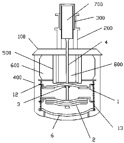
[0029] An acoustic energy compressor cycle structure, such as Figure 1-4 As shown, the upper side of the connection base 100 is provided with an expansion chamber 300 through an external fixing ring 200, the connection base 100 is coaxially fixed with an outer shell 400 and a power cylinder 500 from the outside to the inside, and the expansion piston 700 is inside the expansion chamber 300 reciprocating motion.

[0030] There is also a copper heat dissipation part on the external fixing ring, which has a better heat dissipation effect.

[0031] The outside of the power cylinder 5 is provided with a coil structure 600. This coil structure is adopted with reference to the coil structure in the existing sound energy compressor. Its purpose is to cooperate with the power piston. When the power is on, a magnetic field is generated to make the power piston 800 in the power cylinder reciprocate. sports.

[0032] The expansion piston passes at its underside through the power piston...

Embodiment 2

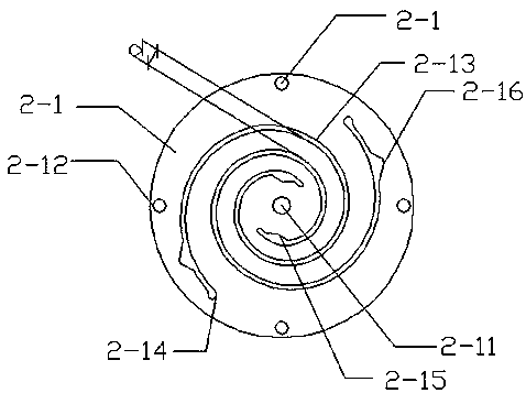
[0047] The width of the back-shaped hollow grooves 2-13 is 11mm, and the groove body spacing d between adjacent round-shaped hollow grooves 2-13 is set to gradually increase outwards, and the innermost groove body spacing d is 4mm, specifically d+0.4 The dimensions in mm are increased.

Embodiment 3

[0049] The width of the back-shaped hollow grooves 2-13 is 8mm, and the groove body spacing d between adjacent round-shaped hollow grooves 2-13 is set to gradually increase outwards, and the innermost groove body spacing d is 4mm, specifically d+0.8 The dimensions in mm are increased.


PUM


Abstract

The invention discloses a sound energy compressor cycle structure. The upper side of a connection base is provided with an expansion air chamber through an external fixing ring, and an outer shell anda power air cylinder are coaxially fixed to the connection base from exterior to interior; the outer side of the power air cylinder is provided with a coil structure; an expansion piston does reciprocating motion in the expansion air chamber, the lower side of the expansion piston penetrates through a power piston which is coaxial with the expansion piston and is located in the power air cylinderto be fixed to a piston supporting structure, and the power piston is also fixed to the piston supporting structure; the piston supporting structure can fix a plate spring through a plate spring fixing structure; and the middle of the plate spring is coaxially connected with the power piston and the expansion piston, and the periphery of the plate spring is subjected to multi-point fixing. According to the sound energy compressor cycle structure, the expansion chamber located on the upper side communicate with the power air cylinder located on the lower side, and connection is simple and goodin effect; and the piston supporting structure adopts the multi-point supporting mode to support the center of the power piston and the center of the expansion piston by adopting the multi-point supporting mode through the plate spring, the piston reciprocating motion stability can be effectively improved, accordingly, the cycle efficiency of a compressor is high, and the action effect is good.

Description

technical field [0001] The invention relates to the technical field of compressors, in particular to a circulation structure of an acoustic energy compressor. Background technique [0002] The sound energy compressor is essentially a device that uses mechanical energy to generate a temperature difference and moves axially in its housing through a moving mechanism. Therefore, during the operation of the sound energy compressor, axial vibration will be generated. The operating environment and the operating safety of the motor will have a certain impact. [0003] During the reciprocating motion of the piston of the compressor, the friction between the cylinder and the piston will cause friction loss, which will affect the stability and working efficiency of the system. Contents of the invention [0004] In order to solve the above problems, the present invention provides a sound energy compressor cycle structure, the expansion chamber on the upper side and the power cylinder...

Claims


Application Information

Patent Timeline
Patent Type & Authority Applications(China)
IPC IPC(8): F04B35/04F04B39/00F04B39/06F16F15/04
CPCF04B35/04F04B39/0044F04B39/06F16F15/046
Inventor 宓锋
Owner SHANGHAI LONGBIN PLASTIC PROD
Why Eureka
Try Eureka