
Two-stage plane movable tooth speed reducer coupled by hollow movable tooth frame

A technology of movable gear reducer and movable gear frame, which is applied in the direction of gear transmission, belt/chain/gear, mechanical equipment, etc., which can solve the problems of large axial size and large power loss of the transmission structure, and achieve good dynamic balance , Stable transmission ratio and high transmission precision

Active Publication Date: 2019-11-15
YANSHAN UNIV
View PDF7 Cites 4 Cited by
  • Summary
  • Abstract
  • Description
  • Claims
  • Application Information

AI Technical Summary

Problems solved by technology

However, the existing transmission structure has a large axial dimension, and the power loss in the process of input and output is large

Method used


Image

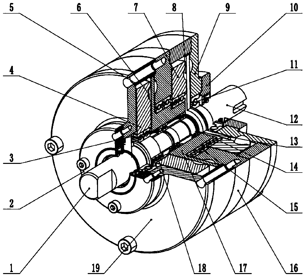
  • Two-stage plane movable tooth speed reducer coupled by hollow movable tooth frame
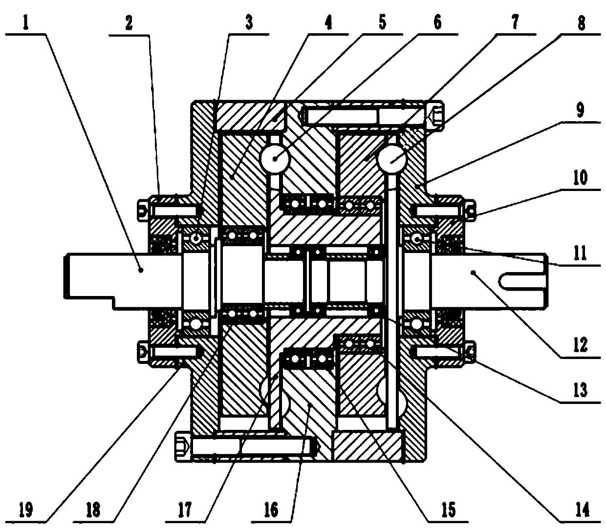
  • Two-stage plane movable tooth speed reducer coupled by hollow movable tooth frame
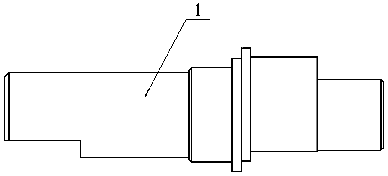
  • Two-stage plane movable tooth speed reducer coupled by hollow movable tooth frame

Examples


Embodiment Construction

[0032] The following will clearly and completely describe the technical solutions in the embodiments of the present invention with reference to the accompanying drawings in the embodiments of the present invention. Obviously, the described embodiments are only some, not all, embodiments of the present invention. Based on the embodiments of the present invention, all other embodiments obtained by persons of ordinary skill in the art without making creative efforts belong to the protection scope of the present invention.

[0033] The object of the present invention is to provide a double-stage planar movable gear reducer coupled with a hollow movable gear frame, so as to solve the above-mentioned problems in the prior art and reduce the power loss at the input and output terminals of the primary and secondary stages. At the same time, through the optimization and innovation of the existing structure, the output of the first stage and the input of the second stage are integrated i...


PUM


Abstract

The invention discloses a two-stage plane movable tooth speed reducer coupled by a hollow movable tooth frame, and relates to the technical field of mechanical transmission. The two-stage plane movable tooth speed reducer coupled by the hollow movable tooth frame comprises an input shaft and an output shaft; a first-stage shock wave device and the input shaft are designed in a split mode; the output torque of the input shaft is transmitted through a rotating arm bearing; the first-stage output and the second-stage input are integrally designed into a first-stage hollow movable tooth frame; a second-stage shock wave device and the first-stage hollow movable tooth frame are designed in a split mode; the output torque of the first-stage hollow movable tooth frame is transmitted through the rotating arm bearing as well; first and second-stage central wheels are fixed; the output shaft serves as the output end of the whole speed reducer; the right end of the input shaft and the left end ofthe output shaft extend into a hole of the first-stage hollow movable tooth frame through matching with a bearing; a first-stage transmission input end is the input shaft, and the first-stage hollow movable tooth frame is the output end; the second-stage transmission input end is the first-stage hollow movable tooth frame; and the second-stage transmission output end is the output shaft. The two-stage plane movable tooth speed reducer is stable in transmission, high in input-output end rigidity, small in self-excitation force and compact in axial structure.

Description

technical field [0001] The invention relates to the technical field of mechanical transmission, in particular to a double-stage planar movable gear reducer coupled with a hollow movable gear frame. Background technique [0002] With the continuous development of research on movable tooth transmission, many transmission structure forms have appeared, which can be roughly divided into two categories: swing movable tooth transmission and mobile movable tooth transmission according to the structural characteristics. Planar movable tooth transmission is a very representative transmission type in mobile movable tooth transmission. It has the advantages of good dynamic balance, wide range of transmission ratio, high transmission precision and high efficiency, and has a compact axial structure compared with other transmission types. , The structure can be subdivided into various forms, and there is no need for a constant speed output mechanism. It has a certain application potentia...

Claims


Application Information

Patent Timeline
Patent Type & Authority Applications(China)
IPC IPC(8): F16H1/32F16H49/00
CPCF16H1/32F16H49/001
Inventor 许立忠孙宇军
Owner YANSHAN UNIV
Learn More