
Polarizing beam splitter, manufacturing method thereof, and polarization beam splitting method

A polarization beam splitter, polarization extinction ratio technology, applied in instruments, optical components, optics, etc., can solve the problems of wide bandwidth, narrow bandwidth, size limitation, etc., and achieve the effect of flexible size and symmetrical output

Active Publication Date: 2021-07-09
UNIV OF SCI & TECH OF CHINA
View PDF3 Cites 0 Cited by
  • Summary
  • Abstract
  • Description
  • Claims
  • Application Information

AI Technical Summary

Problems solved by technology

The following types are mainly used at home and abroad, and their characteristics and disadvantages are listed respectively: 1. Birefringent polarizing beam splitter, based on birefringence and total reflection, has very good performance, and the bandwidth ranges from ultraviolet to near-infrared , the extinction ratio of reflected light and transmitted light is very high, the disadvantage is that the price is relatively expensive, and is limited by size; 2. Wire grid polarizing beam splitter, based on diffraction, the bandwidth is from infrared to far infrared, transmission The extinction ratio of light and reflected light is not high, and the biggest disadvantage is that it is only feasible for the infrared region; 3. Thinfilm plate-cube, based on thin film interference, has the disadvantage of narrow bandwidth
Therefore, for an ideal PBS with wide bandwidth, large viewing angle, and high extinction ratio requirements for reflected light and refracted light, only birefringence-based polarization beam splitters can meet the requirements, but they are expensive and limited by size.

Method used


Image

  • Polarizing beam splitter, manufacturing method thereof, and polarization beam splitting method
  • Polarizing beam splitter, manufacturing method thereof, and polarization beam splitting method
  • Polarizing beam splitter, manufacturing method thereof, and polarization beam splitting method

Examples


preparation example Construction

[0045] Based on this, after determining the number of layers and the thickness of optical film material, Dove prism material, coating film, the present invention further provides a kind of preparation method of above-mentioned polarization beam splitter, comprises the steps:

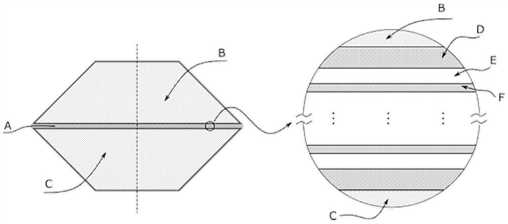
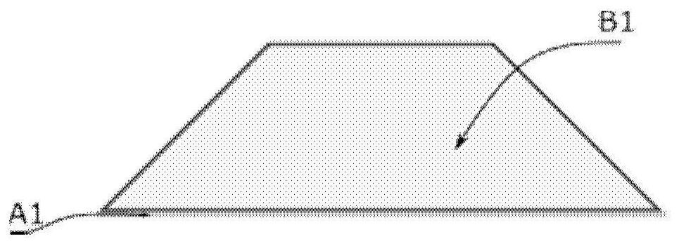
[0046] The multilayer optical film A is divided into two parts, which are respectively coated on the bottom surfaces of two Dove prisms B and C to form a image 3 the structure shown;

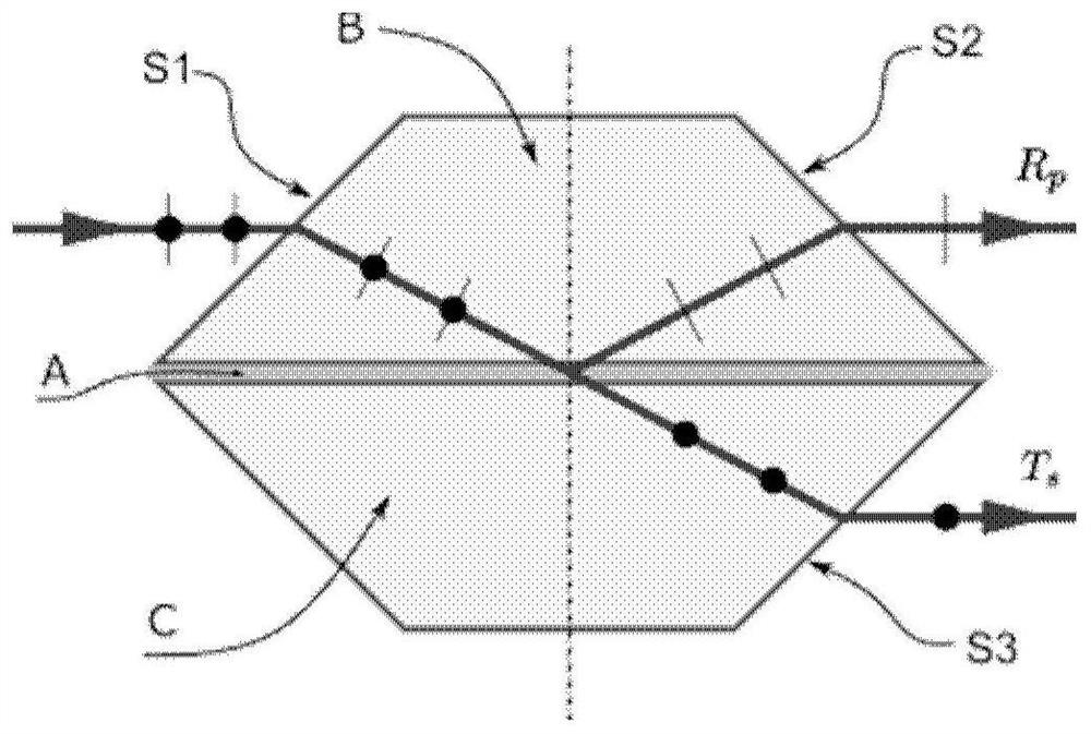
[0047] Then the bottom surfaces of the two coated Dove prisms are facing each other, and assembled into such a figure 1 Polarizing beam splitter shown.

[0048] Among them, due to the requirements of the bonding process, the optical surface shape of the bottom surface of the Dove mirror has certain requirements, and generally needs to reach the order of λ / 10, where λ is the typical wavelength of the polarizing device.

Embodiment 1

[0053] High performance PBS from UV to NIR (350nm–1800nm). Two Dove prisms coated on the bottom surface are assembled into a component using photoresist or gluing process. The two bottom surfaces need photoresist in the subsequent process, so the precision of the processed surface needs to be relatively high, reaching λ / 10, and other light-transmitting surfaces such as the incident surface, exit surface and top surface can reach λ / 4. The two trapezoidal faces are opaque, so there is no face shape requirement. The base material of the Dove prism is Al 2 o 3 . The Dove prism of this embodiment adopts typical dimensions, the bottom surface is 44.94mm long and 12.7mm wide, the top surface is 19.54mm long and 12.7mm wide, and the height between the bottom surface and the top surface is 12.7mm. Scale scales the size. The dimensions are for Al 2 o 3 The base can make the parallel light incident from the midpoint of the hypotenuse of the trapezoid approximately reach the midpoi...

Embodiment 2

[0059] If Ta 2 o 5 Replace ZrO 2 As a material with a high refractive index, this embodiment gives the corresponding coating parameters. Ta 2 o 5 Refractive index curve see Figure 11 , Figure 12 and Figure 13 is to use Ta 2 o 5 Rs and Tp as a function of wavelength for high refractive index films. Among them, initial refers to the film thickness according to the previous embodiment 1, and optimized refers to the film thickness according to Ta 2 o 5 The results of the film thickness optimization of the refractive index. The optimized film thickness is shown in Table 2.

[0060] Table 2

[0061]

[0062]


PUM

PropertyMeasurementUnit
lengthaaaaaaaaaa
heightaaaaaaaaaa

Abstract

A polarizing beam splitter and its preparation method, and a polarizing beam splitting method, the polarizing beam splitter includes: two identical Dove prisms, which are opposite to each other and arranged symmetrically at the bottom; and a multilayer optical film coated on two Between the Dove prisms, they are stacked in the form of high and low refractive index interlaced; among them, the incident light parallel to the optical axis of the Dove prisms to a Dove prism, after being transmitted by the Dove prisms, can be transmitted in the multilayer optical Frustrated total internal reflection and film interference are generated at the interface of the film to realize polarization splitting, and the s and p components are output from the two Dove prisms in parallel. The invention realizes the high polarization extinction ratio of the entire wave band from ultraviolet to near infrared, has the advantages of symmetrical input and output, and can be applied to polarized optical fiber devices.

Description

technical field [0001] The invention belongs to the technical field of basic optical components, and in particular relates to a polarization beam splitter, a preparation method thereof, and a polarization beam splitting method, which are feasible for wide bands from ultraviolet to near-infrared bands, and have a high polarization extinction ratio. Background technique [0002] Polarizers and polarizing beam splitters are both optical components widely used in optical instruments, lasers, electro-optic displays, optical recorders, etc. In polarizers only reflected light is transmitted and used, whereas in polarizing beam splitters (PBS) both transmitted and reflected light are equally important. In principle, any physical and chemical differential influence on the orthogonal components of unpolarized light can be used as a PBS construction. Various forms of polarization beam splitters are constructed by using Brewster's angle effect, birefringence effect, thin film interfere...

Claims


Application Information

Patent Timeline
Patent Type & Authority Patents(China)
IPC IPC(8): G02B27/28G02B1/00G02B1/02
CPCG02B1/00G02B1/02G02B27/283
Inventor 崔金明张昊清黄运锋李传锋
Owner UNIV OF SCI & TECH OF CHINA
Learn More