
Linear polarization quasi-continuous fiber laser

A fiber laser and linear polarization technology, applied in the laser field, can solve the problems of non-adjustable peak pulse width and inability to meet the precision processing requirements of high-reflection materials, etc., and achieve the effect of increasing output power, increasing polarization effect ratio, and broad development prospects

Pending Publication Date: 2022-01-18
JILIN YONGLI LASER TECH
View PDF0 Cites 2 Cited by
  • Summary
  • Abstract
  • Description
  • Claims
  • Application Information

AI Technical Summary

Problems solved by technology

[0004] Quasi-continuous lasers on the market can achieve a pulse width of several microseconds to tens of microseconds by adjusting the frequency and duty cycle, and quasi-continuous lasers on the market can achieve several The pulse width is on the order of microseconds to tens of microseconds, and the common structure is that the control circuit system is connected to the pump source, drive system and feedback system respectively, which can achieve high peak power ms pulse laser output and can replace the lamp pump on the market Pu YAG laser, but the shortcomings of this long-pulse quasi-continuous laser are also obvious. Its polarization state is random and the peak pulse width of the pulse is not adjustable when the pulse width reaches the order of microseconds. These shortcomings make the market Quasi-CW fiber lasers on the market cannot meet the precision processing requirements of some high-reflective materials

Method used


Image

  • Linear polarization quasi-continuous fiber laser
  • Linear polarization quasi-continuous fiber laser
  • Linear polarization quasi-continuous fiber laser

Examples


Embodiment Construction

[0024] The present invention will be described in further detail below in conjunction with the accompanying drawings.

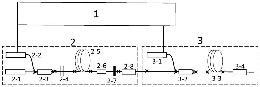
[0025] A linearly polarized quasi-continuous fiber laser is composed of an electric control drive module 1, a linearly polarized laser module 2 and a laser amplification module 3 in sequence.

[0026] The linearly polarized laser module 2 includes an indicating light device 2-1, N pump lasers 2-2, a first polarization maintaining beam combiner 2-3, a polarization device 2-6, a polarization maintaining high reflection grating 2-4, a polarization maintaining Low reflection grating 2-7, first polarization maintaining gain fiber 2-5, first stripper 2-8. The output end of the indicating light device 2-1 is fused with the signal input end of the first polarization-maintaining beam combiner 2-3; the first polarization-maintaining beam combiner 2-3 has N+1 input optical fibers, and the N pump lasers 2-2 are fused with N input fibers of the first polarization-maintai...


PUM


Abstract

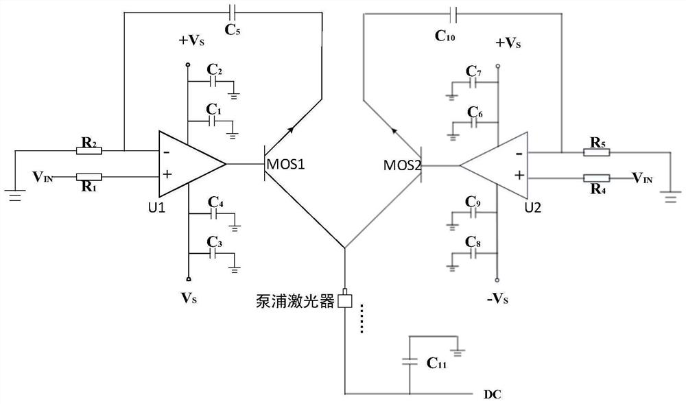
The invention provides a linear polarization quasi-continuous fiber laser and relates to the technical field of laser. In order to solve the problems in the prior art, the laser comprises an electric control driving module, a linear polarization laser module and a laser amplification module, and the electric control driving module comprises a direct current power supply DC, a resistor R1, a resistor R2, a resistor R4, a resistor R5, a capacitor C1, a capacitor C2, a capacitor C3, a capacitor C4, a capacitor C5, a capacitor C6, a capacitor C7, a capacitor C8, a capacitor C9, a capacitor C10, a capacitor C11, an MOS tube MOS1, an MOS tube MOS2, a feedback amplifier U1 and a feedback amplifier U2. The linear polarization laser module comprises an indicator light device, N pump lasers, a first polarization-maintaining beam combiner, a polarization-maintaining high-reflection grating, a first polarization-maintaining gain optical fiber, a polarization device, a polarization-maintaining low-reflection grating and a first stripper, and the amplification module comprises M pump lasers, a second polarization-maintaining beam combiner, a second polarization-maintaining gain optical fiber and a second stripper.

Description

technical field [0001] The invention relates to the field of laser technology, in particular to a linearly polarized quasi-continuous fiber laser. Background technique [0002] Fiber lasers have the advantages of good beam quality, high electro-optic conversion efficiency, small size, maintenance-free, long life, etc. In recent years, processing equipment based on fiber laser technology, such as laser marking machines, engraving machines, cutting machines, welding machines, etc. It is widely used in various industries. In recent years, the application demand of quasi-continuous fiber laser has been increasing year by year. Its pulse width is long, the pulse duty cycle is generally about 10%, the peak power is more than ten times of the continuous power, and the pulse energy is high. It is very suitable for drilling and other applications. favorable. At present, it is also widely used in precision sheet metal cutting, drilling and forming of aluminum oxide (polycrystalline ...

Claims


Application Information

Patent Timeline
Patent Type & Authority Applications(China)
IPC IPC(8): H01S3/10H01S3/067
CPCH01S3/10061H01S3/06712
Inventor 孙尚勇张萍娄前峰常锋苏庆超
Owner JILIN YONGLI LASER TECH
Learn More