Eureka AIR delivers breakthrough ideas for toughest innovation challenges, trusted by R&D personnel around the world.

Connecting assembly and conductive terminal thereof

A technology for connecting components and conductive terminals, which is applied in the direction of connection, conductive connection, conductive connection, etc., can solve the problems of increased weight, shortened service life, and increased battery pack volume, and achieve the effect of stable signal acquisition and long service life

Pending Publication Date: 2019-11-15
ALLTOP ELECTRONICS SU ZHOU
View PDF0 Cites 4 Cited by
  • Summary
  • Abstract
  • Description
  • Claims
  • Application Information

AI Technical Summary

Problems solved by technology

Electric vehicles are equipped with a battery management system that monitors the safe operation of the battery. It is mainly used for battery cell voltage, battery cell temperature, energy balance, thermal management, battery pack total voltage, battery pack total current, data analysis, and voice control. Alarms, etc. are monitored; correspondingly, relevant data of various functions need to be collected. At this time, a large number of connectors and transmission lines need to be used for relevant data collection and transmission, which will cause all the space in the battery pack to be occupied by transmission lines, etc. occupy
As a result, not only the size and weight of the battery pack will increase, but the wiring will be more troublesome, the safety performance will be lower, and the energy consumption and cost will also increase accordingly.
[0003] The conductive terminal of the traditional connection component is electrically connected to the battery core of the battery pack, but the battery core will have a certain tolerance when it expands and contracts during the charging and discharging process or is affected by temperature, and it will also be subject to a certain impact during the vibration process. , which makes the signal acquisition unstable and shortens the service life

Method used


Image

  • Connecting assembly and conductive terminal thereof
  • Connecting assembly and conductive terminal thereof
  • Connecting assembly and conductive terminal thereof

Examples


Embodiment Construction

[0025] The present invention will be described in detail below with reference to the embodiments shown in the accompanying drawings. However, this embodiment does not limit the present invention, and any structural, method, or functional changes made by those skilled in the art according to this embodiment are included in the protection scope of the present invention.

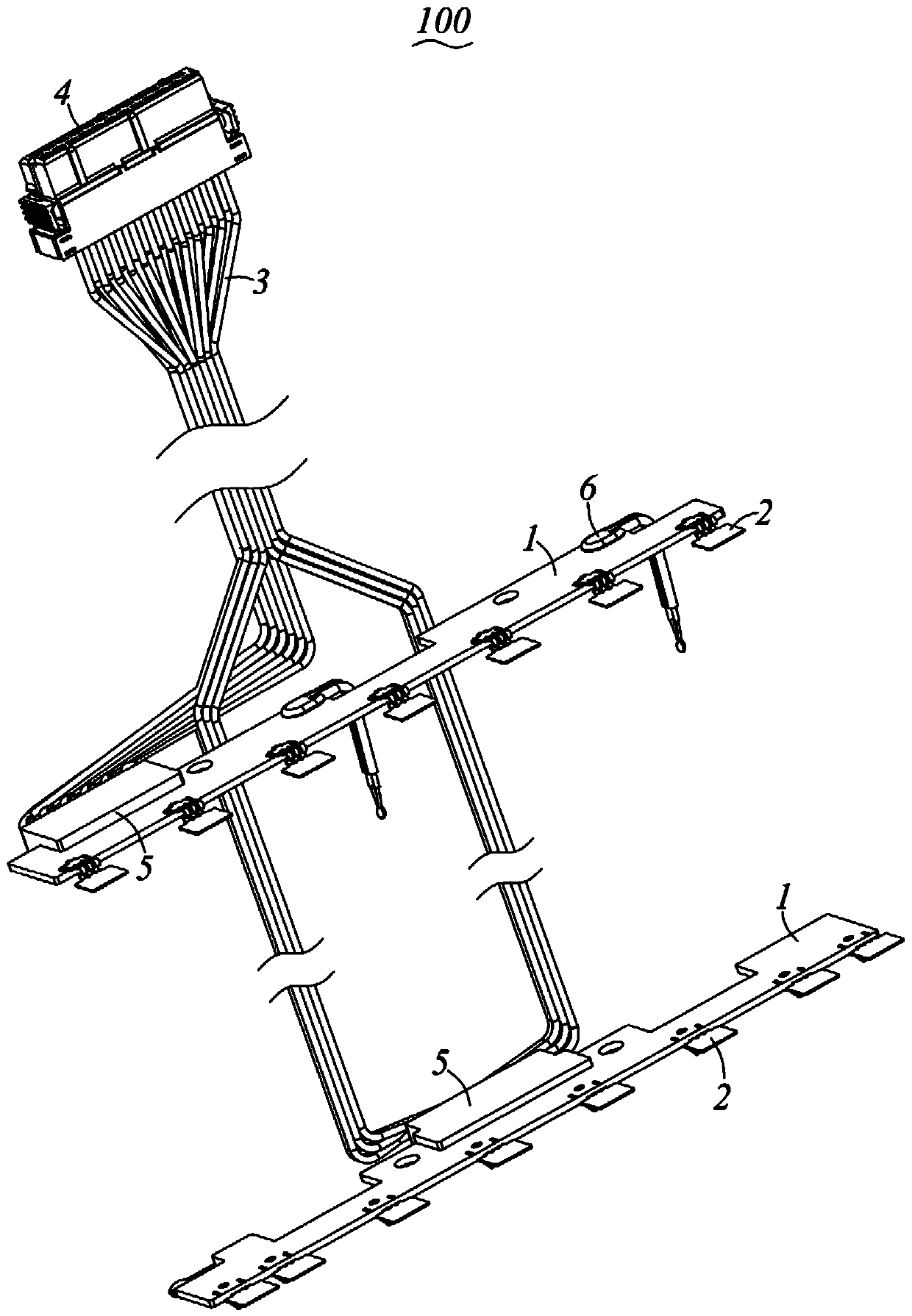
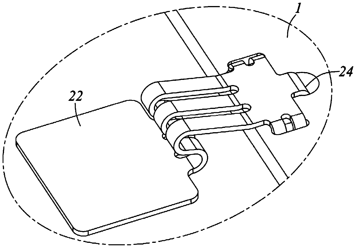
[0026] see Figure 1 to Figure 8 Shown is a preferred embodiment of the connection assembly 100 of the present invention. The connection assembly 100 is used to electrically connect between the battery pack and a battery management system to collect information such as voltage or temperature on the battery pack.

[0027] The connection assembly 100 includes a circuit board 1, a plurality of conductive terminals 2, a plurality of wires 3 and a connector 4 for connecting with the battery management system, and a plurality of the conductive terminals 2 are connected to one end of the circuit board 1 to communicate...


PUM


Abstract

The invention provides a connecting assembly and a conductive terminal thereof. The connecting assembly is used for being electrically connected between a battery pack and a battery management system,and comprises a circuit board, conductive terminals, wires and a connector, wherein the conductive terminals are connected with one end of the circuit board so as to be respectively and electricallyconnected with a plurality of battery cores in the battery pack, the wires are connected with the other end of the circuit board and are electrically connected with the conductive terminals through the circuit board, each conductive terminal comprises a fixing part, a contact part electrically connected with the corresponding battery core and a connecting part connecting the fixing part and the contact part, the fixing part is provided with a base part electrically connected with the circuit board and a fixing pin formed by bending and extending from the base part, the connector is connected to the other ends of the plurality of wires so as to be in butt-joint with the battery management system, and the connecting part is arranged in a bent mode so as to be elastically connected between the base part and the contact part. The connecting assembly and the conductive terminal thereof can stably collect signals.

Description

technical field [0001] The invention relates to a connecting component and a conductive terminal thereof. Background technique [0002] As a new energy vehicle, electric vehicles have become the development direction of the automobile industry. Among them, the battery pack is an important energy source for electric vehicles, and it is particularly important to monitor the performance of the battery pack. Electric vehicles are equipped with a battery management system that monitors the safe operation of the battery. It is mainly used for battery cell voltage, battery cell temperature, energy balance, thermal management, battery pack total voltage, battery pack total current, data analysis, and voice control. Alarms, etc. are monitored; correspondingly, relevant data of various functions need to be collected. At this time, a large number of connectors and transmission lines need to be used for relevant data collection and transmission, which will cause all the space in the ba...

Claims


Application Information

Patent Timeline
Patent Type & Authority Applications(China)
IPC IPC(8): H01R12/58H01R4/48H01R4/02H01M2/20H01M10/42H01M10/48
CPCH01R12/58H01R4/4809H01R4/029H01M10/425H01M10/486H01R2201/26H01M2220/20H01M50/50Y02E60/10
Inventor 张志辉殷定彬
Owner ALLTOP ELECTRONICS SU ZHOU
Why Eureka
Eureka Blog
Learn More